Micro-flow control chip for membrane-free dialysis

A control chip and micro-flow technology, applied in dialysis systems, dialysis, membrane technology, etc., can solve the problems of increasing dialysis efficiency, large cell loss, and low efficiency, and achieve the effects of improving dialysis efficiency, simplifying the structure, and reducing rejection reactions

Pending Publication Date: 2021-12-31
UNIV OF SCI & TECH OF CHINA
View PDF0 Cites 1 Cited by
  • Summary
  • Abstract
  • Description
  • Claims
  • Application Information

AI Technical Summary

Problems solved by technology

[0005] In order to solve the defects in the prior art, the present invention provides a membraneless dialysis microfluidic control chip to solve the problem of low efficiency and large cell loss in existing dialysis, effectively increase the dialysis efficiency and reduce the loss of blood cells

Method used


Image

  • Micro-flow control chip for membrane-free dialysis
  • Micro-flow control chip for membrane-free dialysis

Examples


Embodiment

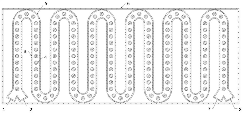
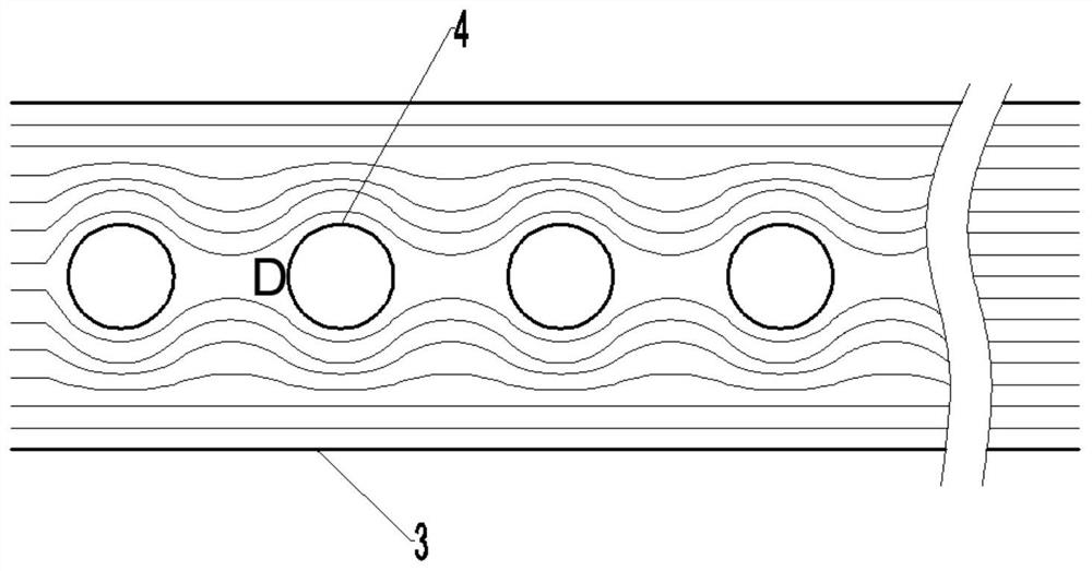
[0026] see Figure 1-2 , the embodiment of the present invention provides a membrane-free dialysis microfluidic control chip, including: blood inlet 1, dialysate inlet 2, straight working flow channel 3, reflection column 4, arc-shaped working flow channel 5, chip housing 6, blood Outlet 7 and dialysate outlet 8.

[0027] Among them, the blood inlet 1, the dialysate inlet 2, the straight working channel 3, the reflection column 4, the arc working channel 5, the blood outlet 7 and the dialysate outlet 8 are all installed in the chip shell 6; the blood inlet 1 and the dialysis The liquid inlet 2 is installed symmetrically at the entrance of the straight working channel 3; the blood outlet 7 and the dialysate outlet 8 are symmetrically installed at the outlet of the straight working channel 3; the straight working channel 3 and the arc working channel 5 Tangentially connected; the reflective column 4 is respectively set in the straight working channel 3 and the arc working chann...


PUM


Abstract

The invention discloses a micro-flow control chip for membrane-free dialysis. The chip comprises a blood inlet, a dialysate inlet, a straight working flow channel, reflection columns, an arc-shaped working flow channel, a chip shell, a blood outlet and a dialysate outlet, the blood inlet, the dialysate inlet, the straight working flow channel, the reflection column, the arc-shaped working flow channel, the blood outlet and the dialysate outlet are all mounted in the chip shell; the blood inlet and the dialysate inlet are symmetrically formed in an inlet of the straight working flow channel; the blood outlet and the dialysate outlet are symmetrically formed in an outlet of the straight working flow channel; the straight working flow channel is tangentially connected with the arc-shaped working flow channel; and the reflection columns are respectively arranged in the straight working flow channel and the arc-shaped working flow channel. According to the technical scheme, the problems that an existing dialysis membrane is low in efficiency and pollutes blood are solved, and cell loss in membrane-free dialysis is effectively reduced.

Description

technical field [0001] The embodiments of the present invention relate to the technical field of membraneless dialysis, and in particular to a microfluidic control chip for membraneless dialysis. Background technique [0002] At present, there are nearly 800,000 dialysis patients in my country. With the acceleration of my country's aging process, the continuous improvement of dialysis quality and dialysis treatment rate, and the improvement and perfection of medical insurance, the number of dialysis patients continues to grow at a rate of about 10% per year. It is estimated that in In 2030, the number of patients requiring dialysis treatment will exceed 3 million. Dialysis is one of the effective measures to prolong the life of patients and improve the quality of life of terminal patients. Hemodialysis machine, commonly known as "artificial kidney", is an extracorporeal hemodialysis device that can replace part of the kidney function, remove harmful substances in the blood, ...

Claims


Application Information

Patent Timeline
Patent Type & Authority Applications(China)
IPC IPC(8): A61M1/14B01D61/24B01D61/28B01L3/00
CPCA61M1/14B01D61/243B01D61/28B01L3/502707B01L2200/12
Inventor 何立群林垚田军见林其钊
Owner UNIV OF SCI & TECH OF CHINA
Why Eureka
Try Eureka