Device for welding nut or the like

A welding device and nut technology, applied in welding equipment, resistance welding equipment, pressure electrodes, etc., can solve the problems of difficult and precise detection, position accuracy error, easy wear of cylinders, etc., and achieve the effect of accurate detection

Inactive Publication Date: 2004-03-03
SMK CO LTD
View PDF3 Cites 16 Cited by
  • Summary
  • Abstract
  • Description
  • Claims
  • Application Information

AI Technical Summary

Problems solved by technology

[0005] However, in the technique as described above, when detecting the protruding position of the positioning pin that freely moves in and out of the lower electrode, the installation defect of the detection nut, etc., it is easy to increase the size of the device itself due to the installation of the detector. When the working rod or connecting rod moves up and down and tilts, its position accuracy is prone to errors, making it difficult to perform accurate detection
For example, for hexagonal nuts, round nuts, cap nuts, and special-shaped welding nuts, the welding defects cannot be detected for nuts with small protrusions. In addition, even in the case of square nuts that are relatively easy to detect, for Welding defects cannot be fully detected
In addition, there is a problem that the positioning pin is easily caught in the through hole of the lower electrode, etc., and it is easy to wear out.
[0006] On the other hand, in order to prevent the connecting rod from tilting when moving up and down, for example, if the gap between the connecting rod and the inner diameter of the cylinder is reduced, for example, when air is sent into the cylinder to prevent the intrusion of splashes , the air cannot circulate smoothly, and tiny splashes easily pass through the cylinder and invade into the cylinder below, which may cause wear and tear on the cylinder and cause deviations in the stroke detection of the cylinder rod.

Method used


Image

  • Device for welding nut or the like
  • Device for welding nut or the like
  • Device for welding nut or the like

Examples


Embodiment Construction

[0046] Hereinafter, the present invention will be described in detail with reference to the accompanying drawings.

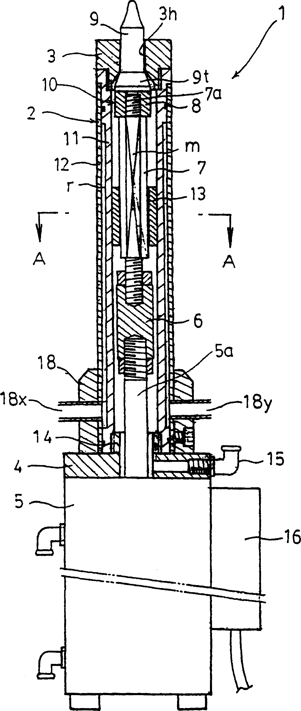
[0047] The welding device 1 such as a nut of the present invention is made so that it can accurately detect the protruding position of the positioning pin, and at the same time, it can prevent spatters generated during welding from entering the cylinder of the electrode holder, thereby improving the life. Such as figure 1 As shown, it has an electrode holder 2 with a double cylinder structure, a lower electrode 3 connected to the top of the electrode holder 2, and a cylinder 5 connected to the bottom of the above-mentioned electrode holder 2 through an insulating material, and the connecting rod 7 is connected to the bottom of the electrode holder 2 through an insulating material. While on the cylinder rod 5a of the above-mentioned cylinder 5, a pin connecting portion 10 is arranged on the top of the connecting rod 7. In this embodiment, a ceramic positioning pi...


PUM

PropertyMeasurementUnit
magnetic flux densityaaaaaaaaaa

Abstract

The present invention relates to a nut positioning pin disposed on a lower electrode for the projection welding of a nut, and an object of the present invention is to increase cooling and positioning accuracy, prevent the entrance of sputtering particles, and increase the detecting accuracy. The present invention comprises an electrode holder (2) of a double-tube structure having a cooling water passage, a guide ring (13) for guiding a coupling rod (7) for vertical movement, an air passage means (m) for preventing the entrance of sputtering particles, a coupling block (28) and a magnetic shield which comprise a magnetic member for preventing a magnetic detecting element from being affected by an external magnetic field.The present invention is capable of accurately guiding cooling water and the coupling rod in the electrode holder and preventing sputtering particles from entering the electrode holder, and of preventing a detector from being adversely influenced by an external magnetic field for increased detecting accuracy.

Description

technical field [0001] The present invention relates to a welding device for preventing welding defects and the like in projection welding of nuts and bolts. Background technique [0002] In the past, when projection welding a nut or a bolt to a steel plate or the like formed with a bottom hole for the screw of the bolt to pass through, it is known that the steel plate or the like is placed on the lower electrode, and the positioning pin is passed through the through hole of the lower electrode. It rises and protrudes upwards from the bottom hole of the steel plate, etc. After positioning the nuts placed on the upper part of the steel plate, etc., the upper electrode is lowered to push the nuts, etc. to the steel plate, etc. In this state, the upper electrode and the lower part By passing electricity between the electrodes, nuts and the like are welded to steel plates and the like. At this time, in order to prevent abnormal situations such as the nuts being placed upside do...

Claims


Application Information

Patent Timeline
Patent Type & Authority Applications(China)
IPC IPC(8): B23K11/14B23K11/30
CPCB23K11/14B23K11/3018B23K11/3081
Inventor 日高胜人
Owner SMK CO LTD
Why Eureka
Try Eureka