Cushioning body for glass substrate and packing body using the cushioning body

A technology for glass substrates and packaging products, which is applied in the field of buffers, and can solve problems such as easy failures, wear marks on the surface of glass substrates, and L-shaped buffers that are not suitable for automation.

Inactive Publication Date: 2004-03-17
ASAHI KASEI KK
View PDF0 Cites 10 Cited by
  • Summary
  • Abstract
  • Description
  • Claims
  • Application Information

AI Technical Summary

Problems solved by technology

In particular, from the viewpoint of saving labor, automatic packaging equipment and unsealing equipment have been introduced recently, but the above-mentioned problems are prone to failure, and it has been pointed out that the L-shaped buffer body is ac

Method used


Image

  • Cushioning body for glass substrate and packing body using the cushioning body
  • Cushioning body for glass substrate and packing body using the cushioning body
  • Cushioning body for glass substrate and packing body using the cushioning body

Examples


reference example 1

[0091] (Glass base board)

[0092] Mother glass for liquid crystal displays

[0093] Size: 600mm×720mm

[0094] Thickness: 0.7mm

[0095] (Foam)

[0096] Resin material:

[0097] The expansion ratio is 20cm 3 / g of ethylene-propylene random copolymer; average particle size of resin foam particles: 3.6mm

[0098] Fusion ratio: 86%

[0099] Compression elasticity index: 549N / cm 2
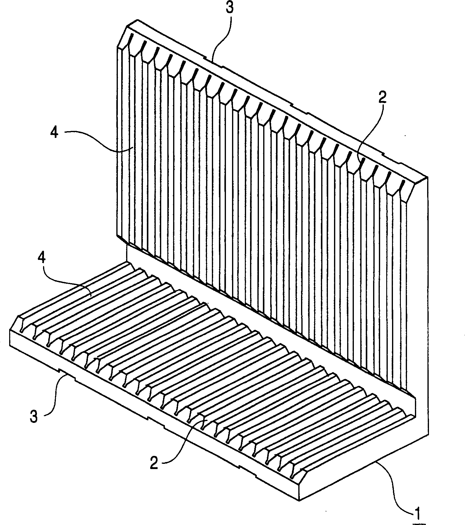
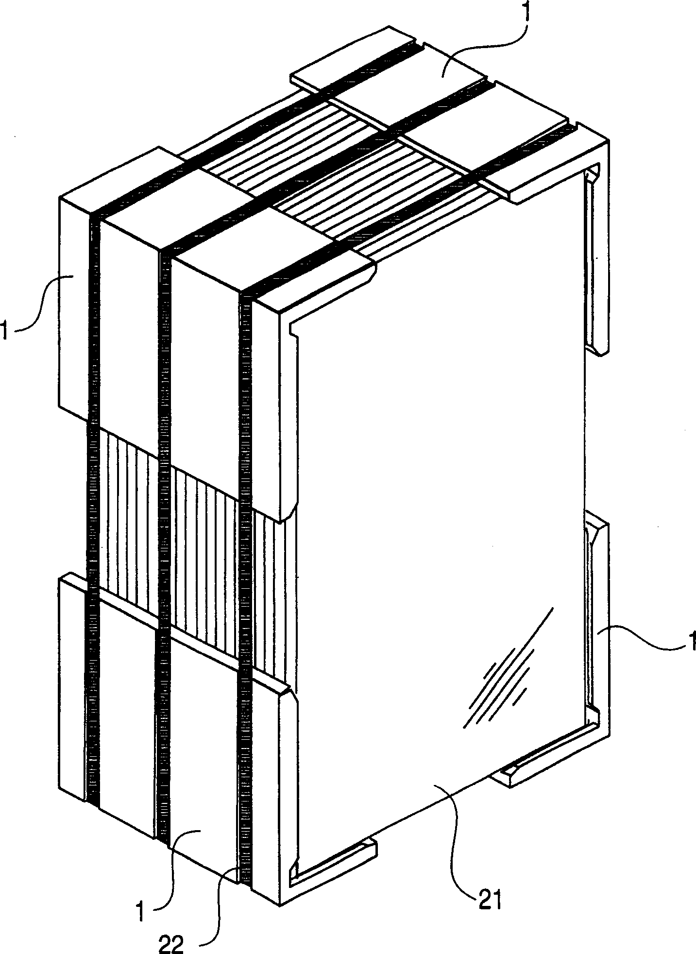
[0100] (buffer)

[0101] Number of glass substrates to be packed: 26

[0102] Dimensions:

[0103] Short side: 250mm

[0104] Long side: 350mm

[0105] Length (at right angles to short side and long side): 300mm

[0106] Maximum thickness: 32mm

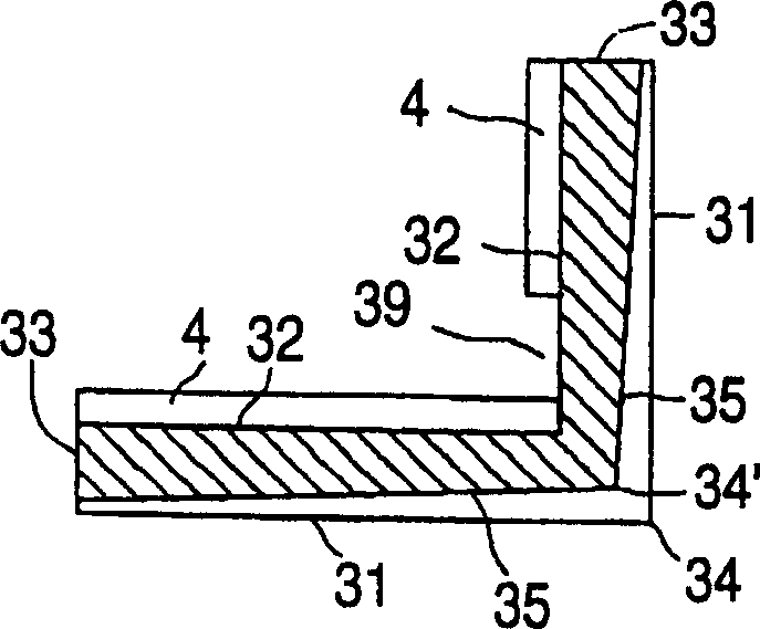
[0107] Base plate insertion slot:

[0108] Width: 2.4mm

[0109] Depth: 12mm

[0110] Spacing: 20mm

[0111] The shape of the protrusion:

[0112] Has a vertical wall of 6.5mm from the bottom of the substrate insertion groove, and a trapezoidal top with a width of 8mm and a height of 5.5mm in the flat part (shape as shown in Figure 4(c))

...

example 2 and comparative example 1

[0123] (Glass base board)

[0124] Mother glass for liquid crystal displays

[0125] Size: 550mm×650mm

[0126] Thickness: 0.7mm

[0127] (Foam)

[0128] Resin material:

[0129] The expansion ratio is 20cm 3 / g and the resin density is 0.930g / cm 3 XLPE

[0130] Average particle size of resin foam particles: 2.8mm

[0131] Fusion ratio: 98%

[0132] Compression elasticity ratio: 412N / cm 3

[0133] Compression elasticity index: 41.2

[0134] (buffer)

[0135] Number of glass substrates to be packed: 12

[0136] Dimensions:

[0137] Short side: 210mm

[0138] Long side: 310mm

[0139] Length (at right angles to short side and long side): 240mm

[0140] Maximum thickness: 23mm

[0141] Base plate insertion slot:

[0142] Width: 1.5mm

[0143] Depth: 7mm

[0144] Spacing: 20mm

[0145] The shape of the protrusion:

[0146] Has a vertical wall of 3.5 mm from the bottom of the substrate insertion slot, and a herringbone top with a height of 3.5 mm (shape as shown...


PUM

PropertyMeasurementUnit
Thicknessaaaaaaaaaa
Average particle sizeaaaaaaaaaa
Thicknessaaaaaaaaaa

Abstract

A cushioning body for glass substrate having an L-shaped section and the thickness of the L-shaped section at the end part larger than the thickness thereof at the corner part, wherein (1) the thickness of the cushioning body is gradually decreased from the end part to the corner part of the L-shaped section with the bottom part of a fixture guide groove taken as a reference by forming the fixture guide groove so that the depth thereof is gradually increased from the end part to the corner part of the L-shaped section, (2) the cushioning device is formed so that the thickness of the cushioning body itself is gradually decreased from both end parts to the corner part of the L-shaped section without forming the fixture guide groove, and (3) a projected part is formed at both outer end parts of the L-shaped section of the cushioning body, whereby a fixture tightening force is prevented from being concentrated to the corner part when the cushioning body is tightened with a fixture.

Description

technical field [0001] The present invention relates to a buffer body for protecting glass substrates, including a glass substrate having electronic parts such as semiconductor devices formed thereon, from damage due to vibration during transportation. The present invention also contemplates a packaged product, wherein a plurality of the above-mentioned glass substrates are packaged together. Background technique [0002] In recent years, electronic or electrical devices, especially liquid crystal displays or plasma displays as a peripheral device for personal computers, and portable terminal devices represented by mobile phones, have developed along with the development of the information technology industry represented by the Internet. Became a device for a surge in production. There is a keen desire to develop technologies related to cushioning bodies for packaging or shipping these devices. Regarding the device, a glass substrate having electronic parts formed thereon ...

Claims


Application Information

Patent Timeline
IPC IPC(8): B65D71/04B65D81/05B65D85/48
CPCB65D81/054B65D85/48B65D71/04B65D2581/055B65D81/113
Inventor 上田康浜田逸男
Owner ASAHI KASEI KK
Why Eureka
Try Eureka