Beating arrangement

A hammer and component technology, applied in the direction of grain processing, etc., can solve the problem of the knife body being useless, and achieve the effect of small wear

Inactive Publication Date: 2004-03-31
WERNER DOPPSTADT UMWELTTECHN
View PDF2 Cites 6 Cited by
  • Summary
  • Abstract
  • Description
  • Claims
  • Application Information

AI Technical Summary

Problems solved by technology

[0004] For both devices, a considerable amount of material, the entire cutter body, is useless if the hammer head is replaced

Method used


Image

  • Beating arrangement
  • Beating arrangement
  • Beating arrangement

Examples


Embodiment Construction

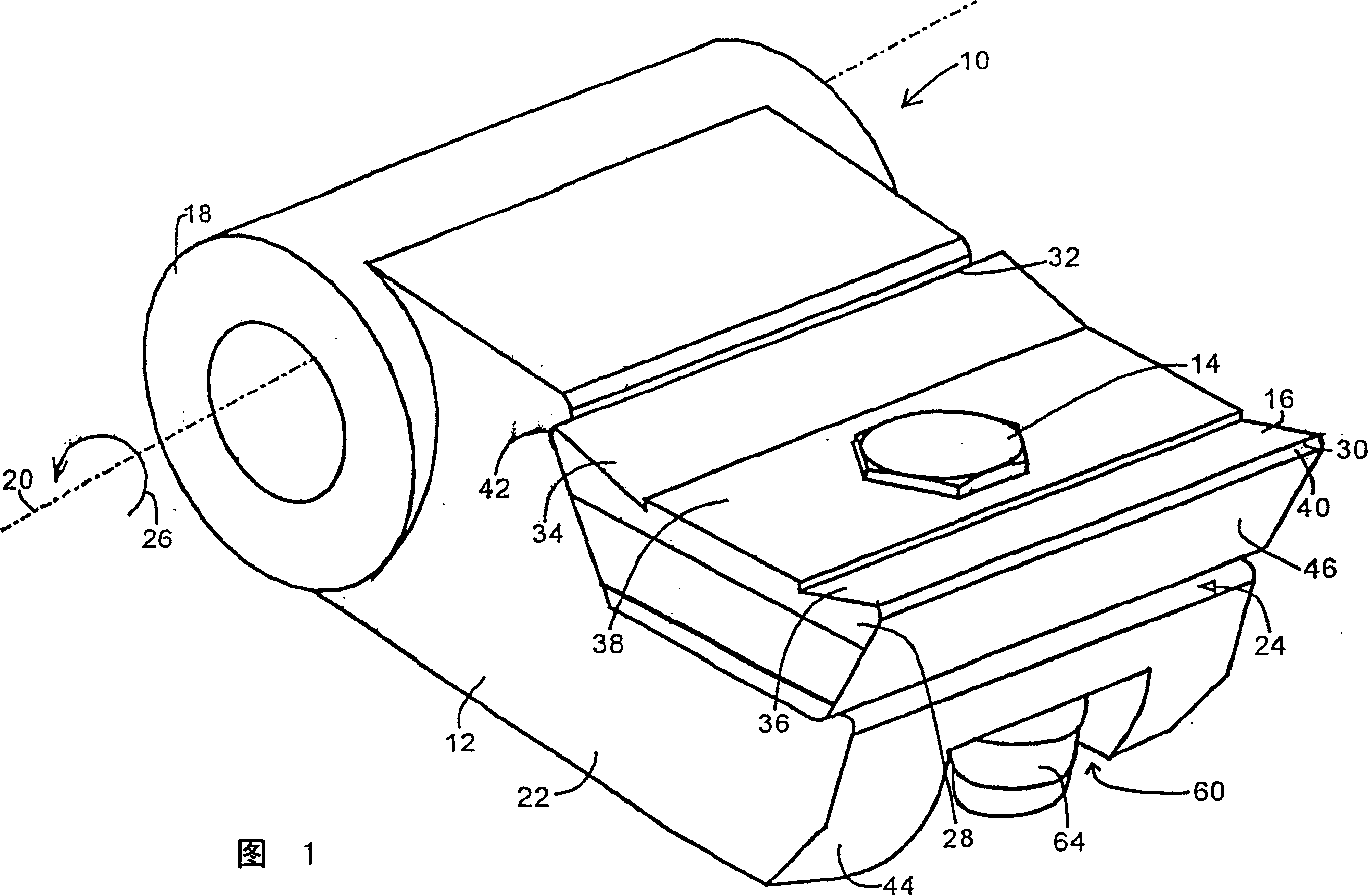
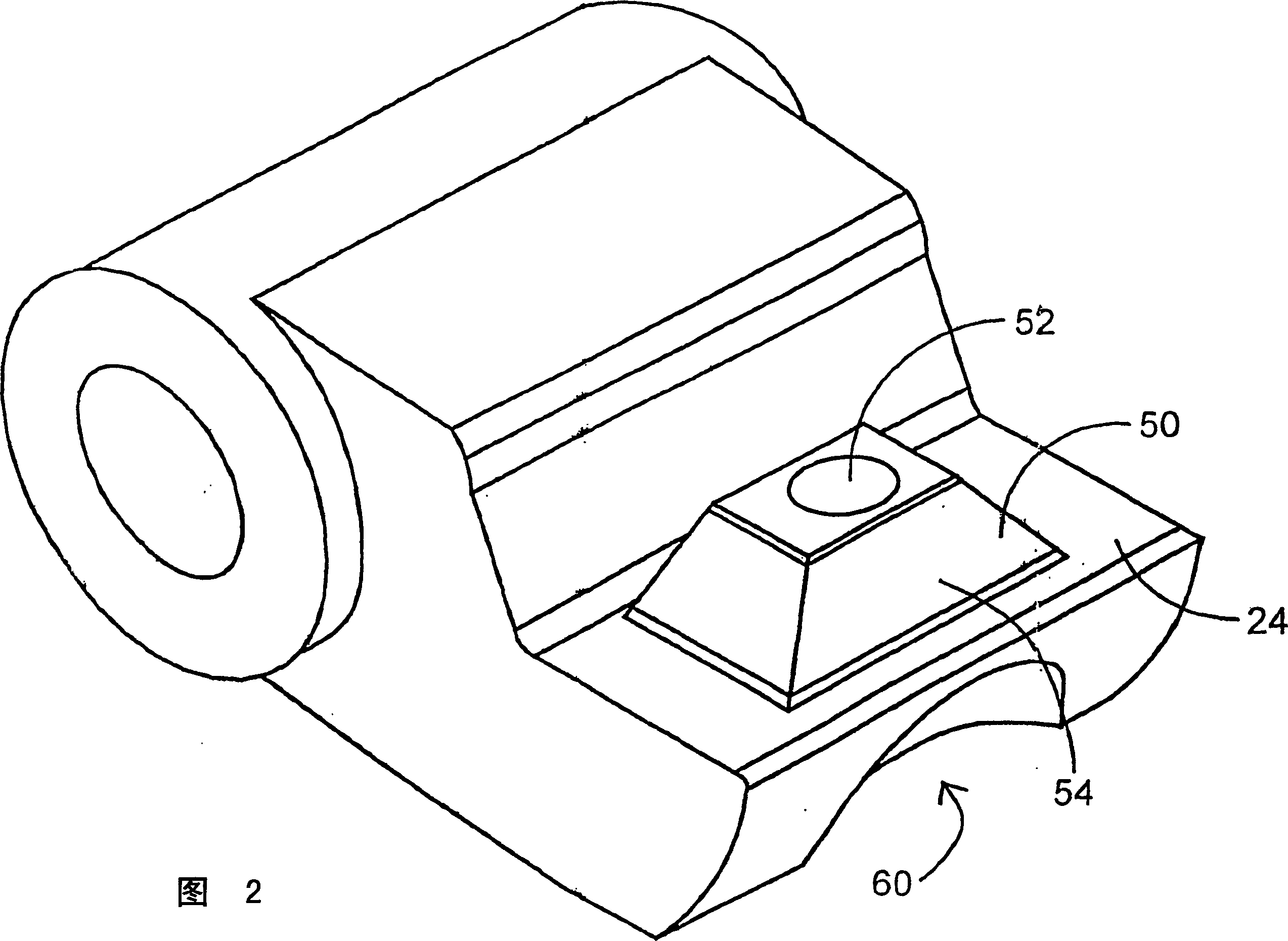
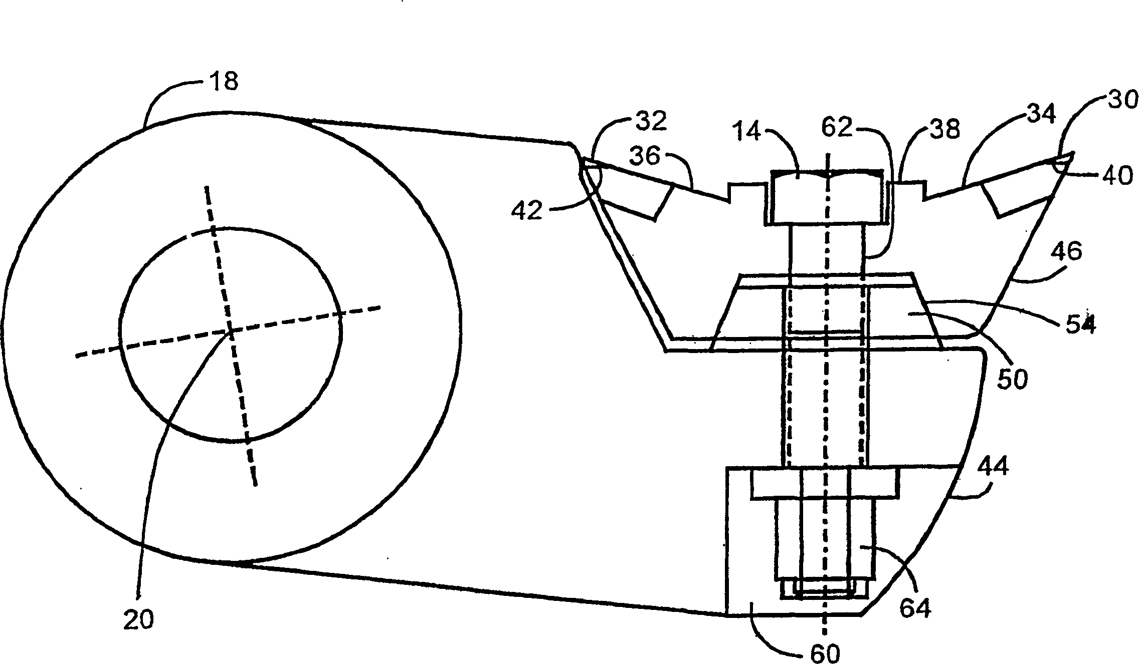
[0017] In Fig. 1, 10 represents a rotary hammer. Rotary hammer 10 comprises a main body 12 and a cutter body 16 screwed thereto by means of a bolt 14, which forms the hammer head. The main body 12 includes a hollow cylinder 18 rotatably mounted about an axis 20 . A protrusion 22 is provided on the hollow cylinder. The protrusion 22 is formed substantially as a step, wherein the "step" has a surface 24 on which the body 16 rests. Surface 24 points in the direction of rotation indicated by an arrow 26 in FIG. 1 . It thus forms the front surface of the body 12 . The knife body 16 is positively seated on the main body 12 . Due to the stepped structure, the cutter body 16 is surrounded on both sides by the main body 12 and forms a unit with it, with no possibility of cutting material getting in between.

[0018] The cutter body 16 has the same trapezoidal cross-section over its entire width. The smaller parallel face 26 of the trapezoid forms the back of the body 16 adjacent ...


PUM


Abstract

The invention relates to a beating arrangement for a rotary shredder, comprising abase body (12) which is rotationally arranged around an axis (20) and a cutting body (16) which is detachably fixed onto a protruding part (22) of the base body. A protruding profile (50) is formed on the front surfacethereof in the direction of rotation whereon the cutting body (16) forms a positive fit. The profile (50) can be embodied in the form of a protruding truncated pyramid, whose base surface lies on the plane of the front surface (24) of the protruding parts. The cutting body (16) can comprise two cutting edges (30, 32) which are bilaterally symmetrical in relation to a surface which extends tangentially in relation to a circumference of rotation. The cutting body can be fixed by means of a screw (14), which extends through the centre of the cutting body and the profile.

Description

technical field [0001] The present invention relates to a hammer assembly for a hammer mill having a body rotatably mounted about an axis and a cutter body releasably secured to a protrusion of the body. Such hammer blades are used as striking tools for hammer mills that crush plastics, wood, and the like. Background technique [0002] German patent DE 3545708C2 discloses a rotary hammer assembly in which the toothed cutter body is releasably fixed with its shaft in a groove. This fastening is achieved by means of a screw which passes through a bore in the main body and the shaft of the cutter body. The shaft is equipped with a flange on its end around a protrusion in the groove. Furthermore, the shaft has a formation protruding into a complementary shaped formation within the groove. In this way, the teeth remain in their position even when strong forces are present. Typically, the hammer head is worn to form an edge in the direction of rotation of the hammer. Due to t...

Claims


Application Information

Patent Timeline
Patent Type & Authority Applications(China)
IPC IPC(8): B02C13/28B02C18/18
CPCB02C18/18B02C13/28
Inventor W·多普斯塔德特
Owner WERNER DOPPSTADT UMWELTTECHN
Why Eureka
Try Eureka