

Guidewire
A wire and coil technology applied to wires. In the field, it can solve the problems of mechanical strength reduction, outer diameter increase, wire deformation, etc., and achieve the effect of improving insertability, improving passability, and reducing thermal influence
- Summary
- Abstract
- Description
- Claims
- Application Information
AI Technical Summary
Problems solved by technology
Method used
Image

Examples
no. 1 approach
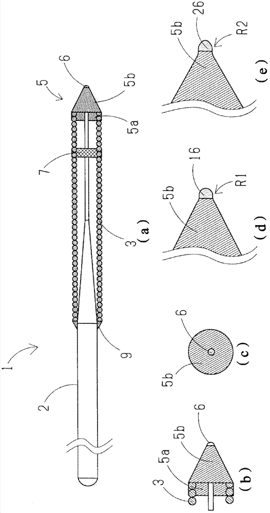
[0043] figure 1 (a) is an overall view showing the lead wire 1 according to the first embodiment of the present invention.
[0044] In addition, for the convenience of explanation, in figure 1 In the description, the left side is referred to as the "proximal end side" and the right side is referred to as the "tip end side".
[0045] Also, for ease of understanding, in figure 1 In , the length direction of the lead wire 1 is shortened, and the overall size of the lead wire 1 is different from the actual one in order to schematically illustrate the whole.
[0046] exist figure 1 In (a), the wire 1 includes: a mandrel 2; a coil member 3 covering the front end of the mandrel 2; In the direction of the proximal end of the most distal portion 5 , the coil component 3 and the mandrel 2 are fixedly connected by an intermediate fixed connection portion 7 , and the proximal end of the coil component 3 and the mandrel 2 are fixedly connected by a proximal fixed connection portion 9 ....
no. 2 approach
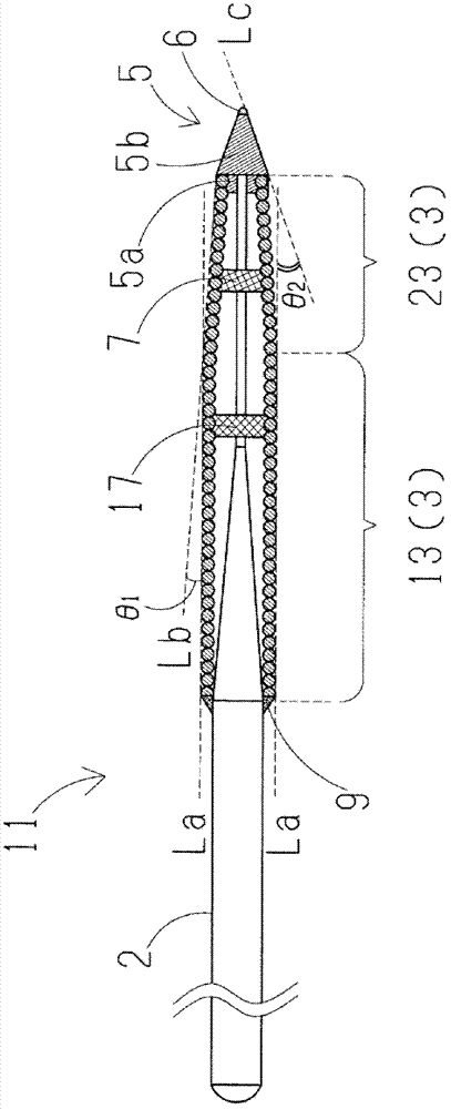
[0078] Next, use figure 2 , the lead wire 11 of the second embodiment will be described centering on differences from the first embodiment. In the drawings, the same reference numerals are used for the same parts as those of the first embodiment.
[0079] Also, for ease of understanding, in figure 2 In order to shorten the longitudinal direction of the lead wire 11 and to schematically illustrate the whole lead wire 11, the overall size of the lead wire 11 is different from the actual one.
[0080] exist figure 2 Among them, the lead wire 11 is different from the first embodiment in that it has the same outer diameter portion 13 with the same coil outer diameter on the base end side of the coil member 3, and has a coil outer diameter portion 13 with a reduced coil outer diameter toward the front end direction on the front end side of the coil member 3. small tapered portion 23 , and has a second intermediate fixed connection portion 17 fixedly connecting the mandrel 2 an...
no. 3 approach
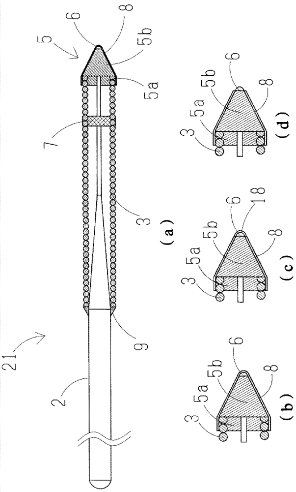
[0088] Next, use image 3 In (a) and (b), the lead wire 21 of the third embodiment will be described focusing on differences from the first embodiment. In the drawings, the same reference numerals are used for the same parts as those of the first embodiment.
[0089] Also, for ease of understanding, in image 3 In (a), the longitudinal direction of the lead wire 21 is shortened, and the overall size of the lead wire 21 is different from the actual one in order to schematically show the whole lead wire 21 . also, image 3 (b) is the image 3 (a) is an enlarged view of the front end portion 5 .
[0090] exist image 3 In (a) and (b), the lead wire 21 is different from the first embodiment in that a lubricious coating layer 8 is applied to the outer periphery of the leading end portion 5 . Also, in the third embodiment, according to image 3 In (b), the lubricious coating layer 8 is coated on the outer peripheries of the proximal-side most distal portion 5 a , the outer di...
PUM
 Abstract
Description
Claims
Application Information