Anti-polarizing mode chromatic dispersion (PMD), system

A pulley, radius technology, applied in the field of anti-PMD system, can solve the problem of high fiber PMD

Inactive Publication Date: 2004-04-07
ALCATEL LUCENT SAS
View PDF2 Cites 3 Cited by
  • Summary
  • Abstract
  • Description
  • Claims
  • Application Information

AI Technical Summary

Problems solved by technology

The drawback of this prior art system is that the PMD of the fiber obtained is still too high

Method used


Image

  • Anti-polarizing mode chromatic dispersion (PMD), system
  • Anti-polarizing mode chromatic dispersion (PMD), system
  • Anti-polarizing mode chromatic dispersion (PMD), system

Examples


Embodiment Construction

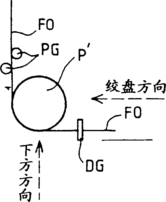
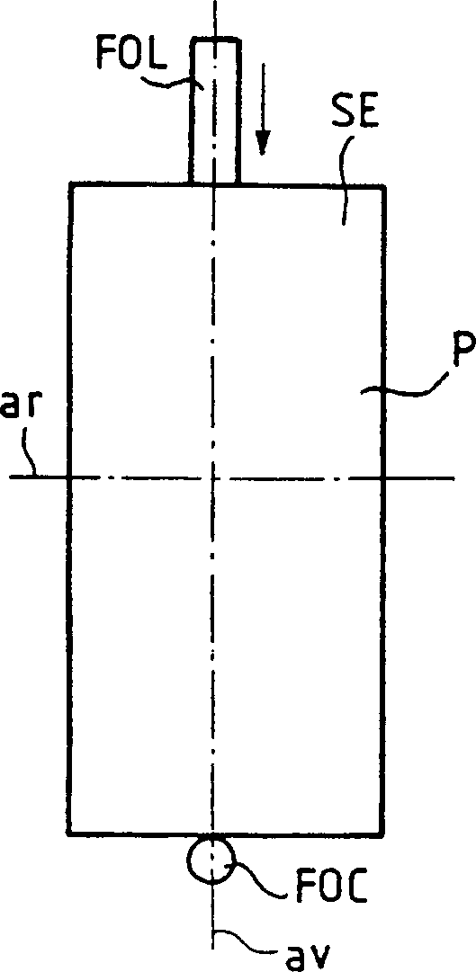
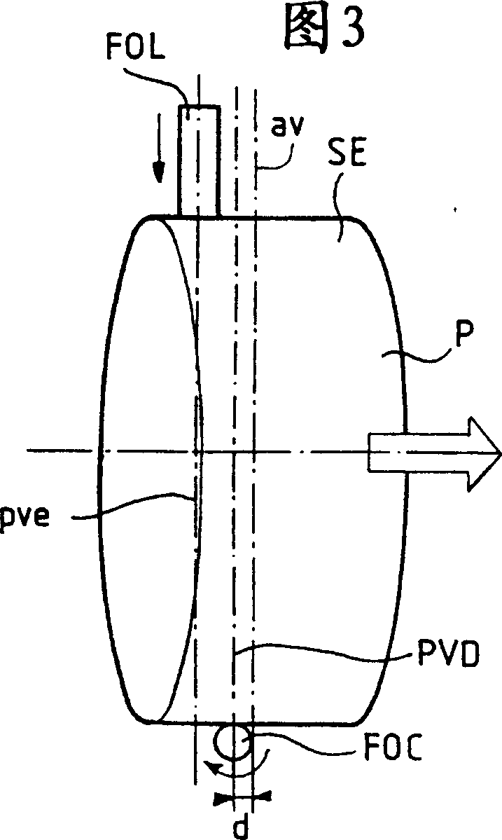
[0010] figure 1 is a schematic illustration of a section of an optical fiber drawing system starting from a preform in which an anti-PMD system according to the present invention is incorporated. figure 1 The section of the fiber drawing system shown is located below the draw tower. The fiber FO coated with two layers of coating moves in the direction indicated by the solid arrow. The optical fiber FO is also guided in vertical movement by guide wheels PG. Subsequently, the fiber FO changes direction while passing the oscillating pulley P'. At the exit of the oscillating pulley P', the optical fiber FO is guided to move horizontally by the guide shaft (guide finger) DG. For simplicity, figure 1 A winch, not shown in , is located behind (downstream) the guide shaft DG. Dashed arrows indicate different viewing directions taken in subsequent views.

[0011] During the fiber drawing process, the different manufacturing stages of the fiber have a significant impact on the pre...


PUM

PropertyMeasurementUnit
radiusaaaaaaaaaa
radiusaaaaaaaaaa

Abstract

Anti-PMD (Polarization Modal Dispersion) system comprises a pulley (P') oscillating in rotation. The pulley applies, during the formation of an optical fiber (FO), alternately in the clockwise and anti-clockwise directions, a torsion couple to the fiber so as to diminish its PMD. At least part of the external surface (SE') of the pulley in contact with the fiber during its formation is convex. An Independent claim is also claimed for the pulley used in the anti-PMD system.

Description

technical field [0001] The field of the invention is that of anti-PMD systems aimed at reducing the PMD of optical fibers during fiber drawing. PMD is polarization modal dispersion. Polarization mode dispersion is a defect of optical fiber because it causes the quality of the signal transmitted in the fiber to be degraded. As the information rate increases in the optical fiber communication network, this defect becomes more and more prominent. Background technique [0002] According to the prior art, it is known to use an anti-PMD system called the SZ system. The system is based on the use of a rotating oscillating flat rim pulley. Such systems are described, for example, in European patent document EP 582405 and European patent document EP 744636, incorporated herein by reference. The SZ system consists of a flat rim pulley. A flat rim pulley is a pulley with a cylindrical outer surface. The SZ system is assembled on the base of the drawing tower, and the optical fibe...

Claims


Application Information

Patent Timeline
Patent Type & Authority Applications(China)
IPC IPC(8): C03B37/03
CPCC03B2205/06C03B37/032C03B2203/19C03B2203/36
Inventor E·莱内K·杜格达格J-F·布里
Owner ALCATEL LUCENT SAS
Why Eureka
Try Eureka