
Injection molding device and member used thereof and surface treatment method

An injection molding device and component technology, applied in sputtering plating, ion implantation plating, coating, etc., can solve the problems of protrusions, incorporation, and poor molding quality of molded products

Inactive Publication Date: 2004-04-14
MAXELL HI TEC +1
View PDF1 Cites 3 Cited by
  • Summary
  • Abstract
  • Description
  • Claims
  • Application Information

AI Technical Summary

Problems solved by technology

[0004] However, since the injection needle and the nozzle body are made of ordinary steel, the detachability with the molding resin is not good.
Because, when sealing with such an injection needle, bubble-like protrusions, burrs, and mold release are likely to occur on the sealing part of the molded product.
In addition, since the detachability with the molding resin is poor, resin will adhere around the injection needle and inside the nozzle body at the end of molding, and the attached resin will be burnt and discolored during injection molding, and its ash will be removed from the mold. The injection needle and nozzle body come off and rush into the mold and mix into the molded product
As a result, there will be disadvantages such as lower product prices, and worse, poor molding quality and low utilization of raw materials in production.
[0005] In addition, since the fluidity of the molding resin on the surface of the molding die is not necessarily good, a resin with a relatively small molecular weight is used, so the mechanical strength of the molded product is not good.
In addition, in order to improve the fluidity of the resin, it is necessary to increase the molding temperature (heating temperature), so there are disadvantages such as increased power consumption.

Method used


Image

  • Injection molding device and member used thereof and surface treatment method
  • Injection molding device and member used thereof and surface treatment method
  • Injection molding device and member used thereof and surface treatment method

Examples


Embodiment Construction

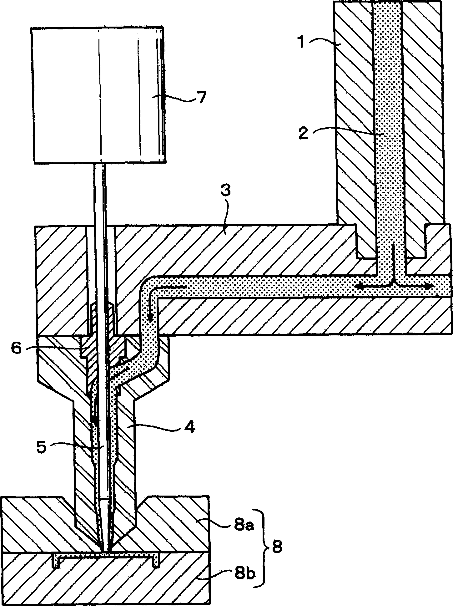
[0040] Hereinafter, embodiments of the present invention will be described with reference to the drawings. figure 1 It is an explanatory drawing of the injection part of the injection molding apparatus of 1st Embodiment.

[0041] 1 in the figure is a gate for supplying molten resin 2 such as ABS resin to the manifold 3, and 4 is a plurality of nozzle bodies installed at the front end of the manifold 3 ( figure 1 Only one nozzle main body 4) is drawn, 5 is a movable injection needle for sealing resin disposed in the nozzle main body 4, 6 is an injection needle guide bush that holds the injection needle 5 at the center of the nozzle main body 4, and 7 is a built-in drive The cylinder of the piston for the injection needle 5, 8 is a molding die, and consists of a fixed side die 8a and a movable side die 8b.

[0042] The molten resin 2 supplied from the gate 1 is divided into the direction of each mold 8 along the manifold 3, and is injected into the mold 8 (cavity) from the fron...


PUM

PropertyMeasurementUnit
Film thicknessaaaaaaaaaa

Abstract

Provided is an injection molding machine which has a long service life and good moldability.Characteristically, at least a surface, which is brought into contact with a resin, of a base material 41 forming a resin passage is covered with a protective film 43 composed of a diamond-like carbon (DLC) containing fluorine.

Description

technical field [0001] The present invention relates to various injection molding devices and components used thereon such as injection needles, molding dies, gates, manifolds, heating cylinders, screws, nozzles, etc. The injection molding device of the protective film and the components used on it and the surface treatment method are related. Background technique [0002] Since the injection needle is disposed inside the nozzle body that injects the molten resin into the mold, the pressure-fed molten resin can be injected into the mold from the front end of the nozzle body through the slit formed between the nozzle body and the injection needle. Then, after entering the holding pressure, the injection needle is moved a little to seal, and then the resin molded product is taken out from the injection molding device and assembled. [0003] In addition, examples relating to molding dies include Patent Document 1 (JP-A-1-234214). [0004] However, since the injection needle a...

Claims


Application Information

Patent Timeline
IPC IPC(8): B29C45/02B29C45/17B29C45/20C23C14/06
CPCB29C45/27
Inventor 平井雄介宫本智之山本悟赤里孝一郎
Owner MAXELL HI TEC
Learn More