Inductance element

A technology of inductive elements and metal parts, applied in the improvement field of its shielding structure, can solve the problems of cumbersome operation, complicated installation, low productivity, etc., and achieve the effect of convenient fixing

Inactive Publication Date: 2004-04-14
MITSUMI ELECTRIC CO LTD
View PDF2 Cites 4 Cited by
  • Summary
  • Abstract
  • Description
  • Claims
  • Application Information

AI Technical Summary

Problems solved by technology

[0005] However, in these prior art, there is a problem that it is necessary to install the parts (shielding plate or magnetic thin plate) with the shielding function on the circuit board other than the inductance element, and the installation is complicated.
In particular, for assembl

Method used


Image

  • Inductance element
  • Inductance element
  • Inductance element

Examples


Embodiment Construction

[0014] Next, an inductance element using the present invention will be described with reference to the drawings.

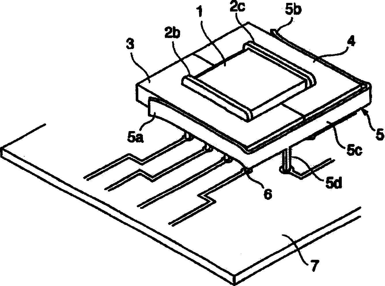
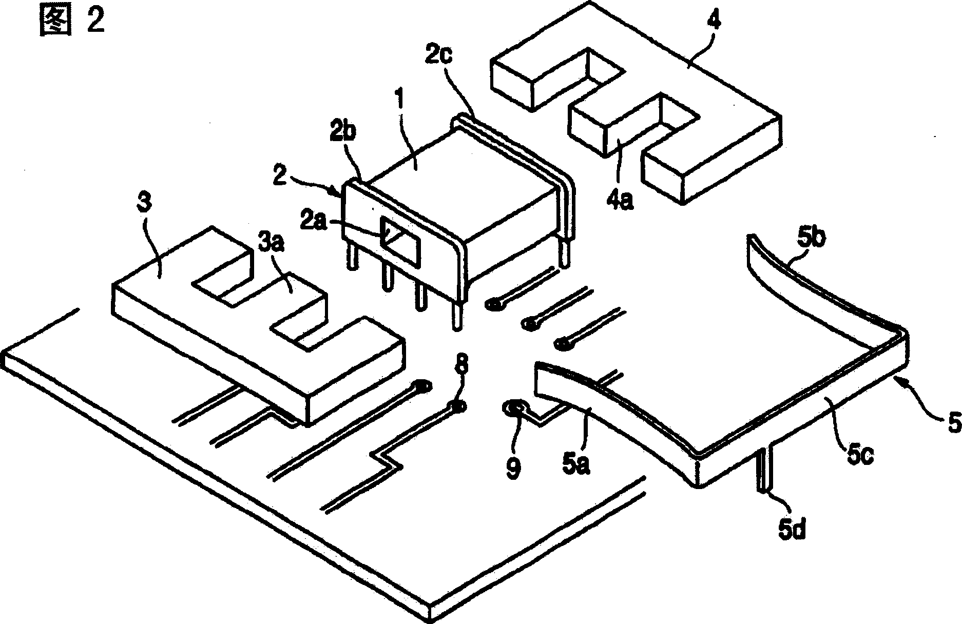
[0015] figure 1 and FIG. 2 is an example of a transformer using the conversion element of the present invention, particularly a transversal magnetic core. figure 1 Fig. 2 shows a situation in which the transformer using the present invention is mounted on a printed circuit board, and Fig. 2 shows a situation in which the transformer using the present invention is disassembled.

[0016] The transformer of this embodiment is composed of a coil bobbin 2, a pair of iron cores 3, 4 and a fixed metal part 5, the coil bobbin 2 is wound with a winding 1 such as a primary coil and a secondary coil, and the iron cores 3, 4 are inserted into the coil bobbin In the coil hole 2a of 2, a fixing metal piece 5 made of metal is used for assembling these iron cores 3, 4.

[0017] The bobbin 2 consists of a molded part, for example of plastic, with flanges 2b, 2c at its ends. The...


PUM


Abstract

To simply realize fixing of cores and countermeasures against noises in an inductance element.The inductance element is mounted to a wiring board. A pair of cores 3, 4 are fitted into a coil bobbin 2, to which a winding is formed. The cores are clipped with a fixing metal fitting 5 made of metals and incorporated. The fixing metal fitting 5 has a shielding function and functions as a shield, to interrupt leakage magnetic fluxes of the inductance element. Also, since a terminal part for fixing to the wiring board 7 is provided to the fixing metal fitting 5, mounting state is reinforced.

Description

technical field [0001] The present invention relates to an inductance element used as a transformer and a line filter etc., especially relates to the improvement of its shielding structure. Background technique [0002] As a transformer used, for example, in a switching power supply, there is known a structure in which an iron core as a magnetic core is assembled with a bobbin around which a primary coil and a secondary coil are wound. In a transformer having such a structure, the end portion of each coil is wound on a terminal pin provided on a bobbin, the terminal pin is inserted into a through hole provided on a printed circuit board, and mounted to the printed circuit board by soldering. board. [0003] However, the above-mentioned converted power supply has greater electromagnetic interference than other electronic components, and there is a danger of electromagnetic waves adversely affecting its surroundings. In particular, the above-mentioned problems have become mo...

Claims


Application Information

Patent Timeline
IPC IPC(8): H01F27/36H01F17/00H01F27/06H01F27/26H01F30/00H01F37/00H05K9/00
Inventor 儿玉繁信
Owner MITSUMI ELECTRIC CO LTD
Why Eureka
Try Eureka