Electric fan and electric dust collector using said fan

A technology of electric fans and motors, which is applied in the fields of vacuum cleaners, engine manufacturing, machines/engines, etc., and can solve the problem that the specific area and shape of the first type of exhaust port are not described in detail relative to the relationship between the air guide components 5

Inactive Publication Date: 2004-05-12
PANASONIC CORP
View PDF1 Cites 11 Cited by
  • Summary
  • Abstract
  • Description
  • Claims
  • Application Information

AI Technical Summary

Problems solved by technology

This fact is well known, but the specific area and shape of the first type of exhaust port (7), the relative posit

Method used


Image

  • Electric fan and electric dust collector using said fan
  • Electric fan and electric dust collector using said fan
  • Electric fan and electric dust collector using said fan

Examples


Embodiment Construction

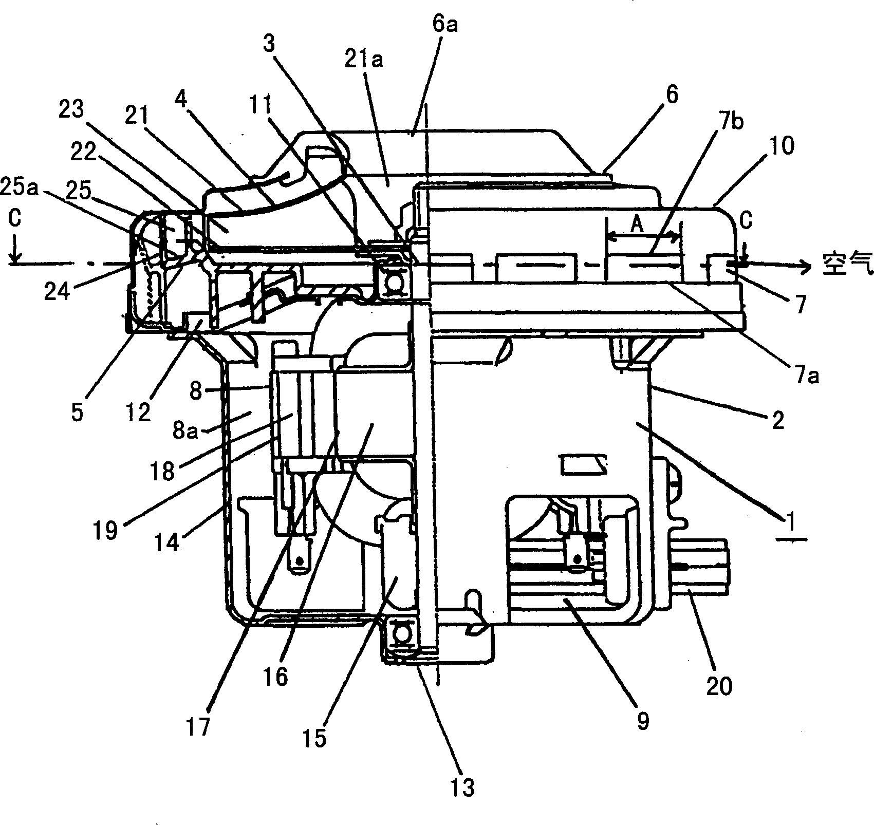
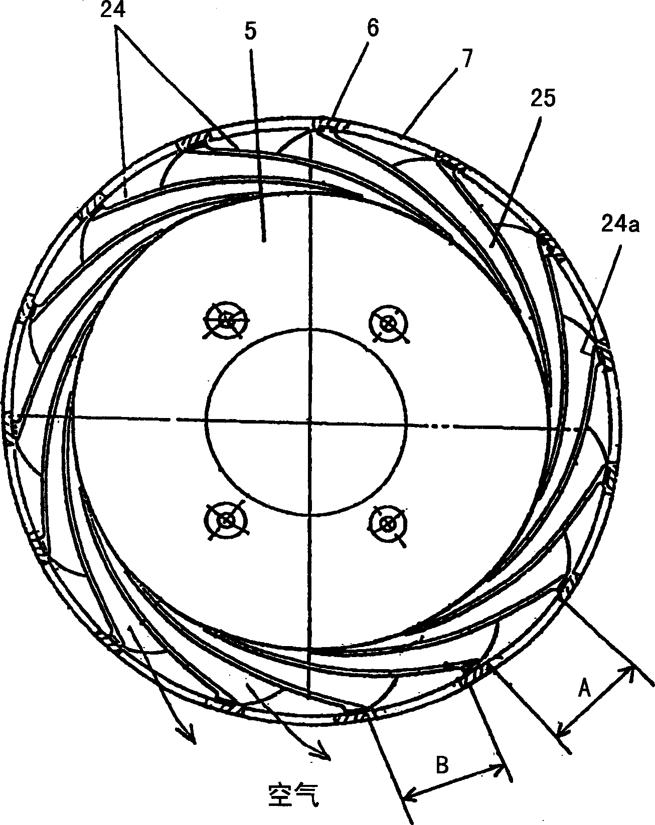
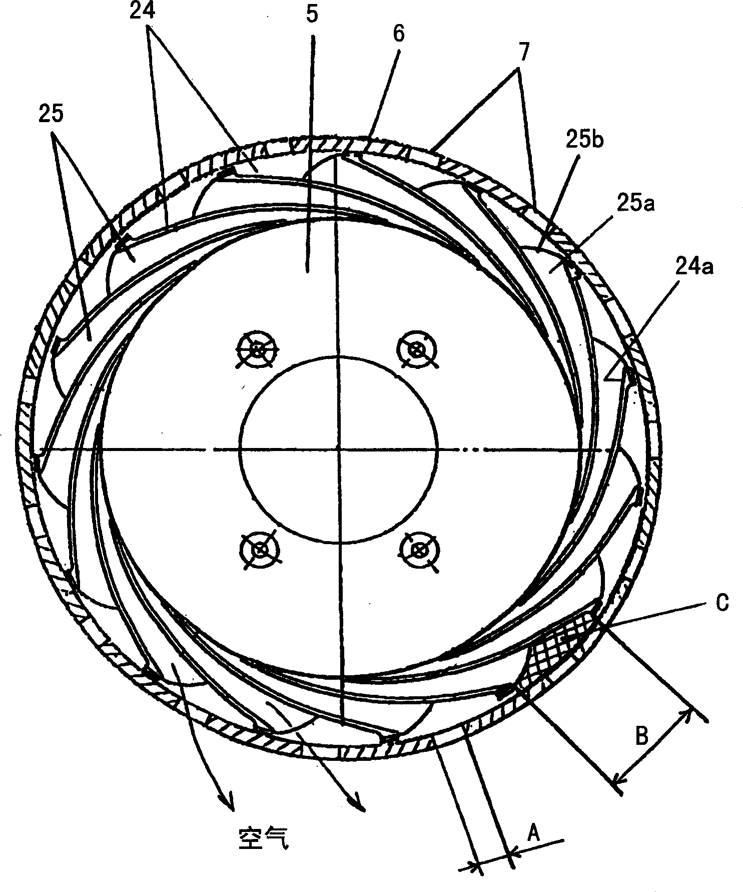
[0026] With the help of figure 1 and figure 2 The first embodiment of the present invention will be described. In the following description, the same parts as those in the conventional device are assigned the same reference symbols and their descriptions are omitted.

[0027] The electric blower 1 is composed of a motor assembly 2 and a fan assembly 10 . The casing of the motor assembly 2 is composed of a first frame 12 supporting the bearing 11 on the load side and a second frame 14 supporting the bearing 13 on the opposite side to the load, and the motor 8 is arranged inside the second frame 14 .

[0028] The motor 8 is composed of a rotor 17 and a stator 19 . The rotor 17 is formed by pressing the armature core 16 formed by laminating the commutator 15 and silicon steel sheets on the rotating shaft 3, fixing it, and then installing a coil (not shown in the figure). The stator 19 is formed by installing coils (not shown in the figure) on the excitation core 18 formed b...


PUM


Abstract

An electric blower (1) includes a stator (19) and a rotor (17). An impeller (4) is fixedly installed on a rotation shaft (3) of the rotor. A casing (6) encloses the impeller (4). The casing is provided with a number of exhaust openings (7) through which a part of an air stream suctioned by the impeller (4) is discharged, wherein each of the exhaust openings (7) is a form of a hole.

Description

technical field [0001] The invention relates to an electric fan and an electric vacuum cleaner using the fan. Background technique [0002] Let's first use Figure 18 To describe the existing electric fan. [0003] Figure 18 shows an electric fan with a turbine 4 installed / fixed on the rotating shaft 3 of the motor assembly 2 . On the outside of the periphery of the turbine 4, there are corresponding air guiding parts 5. 6 is a fan cover, which surrounds the turbine 4 and the air guiding part 5 from the outside, and is installed in an airtight manner. On the outer periphery of the motor assembly 2, an air suction hole 6a is provided in the central part thereof. A plurality of first-type exhaust ports (7) are provided on the outer periphery of the fan cover 6 . In addition, an exhaust port B ( 9 ) is provided in the frame 8 constituting the motor unit 2 . [0004] The operation in the above constitution will be described below. When the turbine 4 installed / fixed on the ...

Claims


Application Information

Patent Timeline
IPC IPC(8): A47L5/22F04D29/44
CPCF04D29/444A47L5/22F05D2250/52
Inventor 德田刚村田吉隆速水祯高森下和久汤朝康裕土屋法宏
Owner PANASONIC CORP
Why Eureka
Try Eureka