Internal antenna

A technology for antennas and planar antennas, applied in the directions of antennas, resonant antennas, slot antennas, etc., can solve problems such as general electrical characteristics, and achieve the effect of simple installation

Inactive Publication Date: 2004-05-12
L K PROD OY
View PDF0 Cites 32 Cited by
  • Summary
  • Abstract
  • Description
  • Claims
  • Application Information

AI Technical Summary

Problems solved by technology

[0005] When the radio in question is very small, the antenna of Fig. 1 has the disadvantage that it has somewhat general electrical characteristics

Method used


Image

  • Internal antenna
  • Internal antenna
  • Internal antenna

Examples


Embodiment Construction

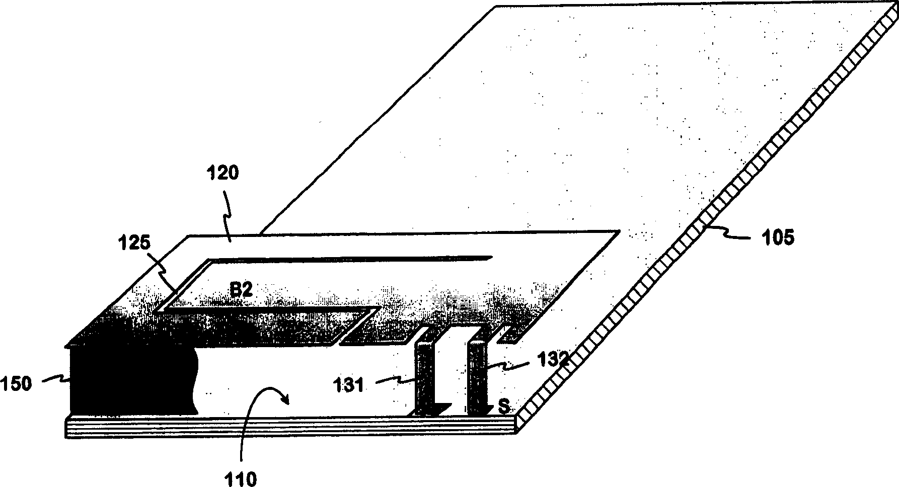
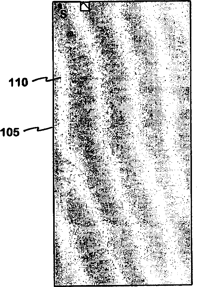
[0021] Figure 2a , 2b The principle of increasing the electrical length of the ground plane according to the invention is illustrated. Figure 2a The circuit board 105 of the structure depicted in FIG. 1 is shown when viewed from the ground plane side. In the upper left corner of the ground plane 110, there is a short-circuit point S for the radiating plane. Since the ground plane has no pattern to change its shape, its electrical length, measured from the short circuit point, is determined by the length of the sides of the rectangular plane. Because the ground plane is relatively small, its electrical length is important because it can radiate at frequencies on the order of the operating frequency, acting like a branch of a dipole antenna.

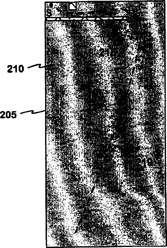
[0022] Figure 2b A printed circuit board 205 is shown, which is similar to the one described above, but now has a slot 215 over the ground plane. In this example, the slot starts on the long side of the ground plane near the short po...


PUM


Abstract

An internal planar antenna for small radio apparatuses, and a radio apparatus. The ground plane (310) of the planar antenna is shaped such that it improves the matching of the antenna. The shaping may be done by means of one or more slots (315, 316) in the ground plane. The slot suitably changes the electrical length of the ground plane as viewed from the short-circuit point (S) so that the ground plane will function as a radiator in an operating band of the antenna. Also the slot (331) in the ground plane can be arranged to function as an additional radiator in an operating band of the antenna. Antenna gain will increase as the matching is improved, and the upper band of a dual band antenna, for example, can be made broader.

Description

technical field [0001] The present invention relates to an internal planar antenna for use with small radio devices. The invention also relates to a radio device using the antenna according to the invention. Background technique [0002] Available space is an important factor in antenna design. It is relatively easy to create a high-quality antenna if there are no size constraints. In radio devices, especially mobile phones, the antenna is preferably placed within the casing of the device for convenience. As devices become smaller, the space available for antennas is shrinking, which means more compact designs are required in antenna design. Another factor contributing to this is that usually an antenna must be able to operate in two or more frequency bands. [0003] In fact, an antenna with satisfactory characteristics installed inside a small device is easiest to realize in a planar structure: the antenna consists of a radiating plane and a ground plane parallel to it....

Claims


Application Information

Patent Timeline
Patent Type & Authority Applications(China)
IPC IPC(8): H01Q1/24H01Q1/48H01Q5/00H01Q5/371H01Q9/04
CPCH01Q9/0421H01Q1/243H01Q1/48H01Q5/0058H01Q9/0442H01Q5/371
Inventor J·米科拉P·安纳马尔
Owner L K PROD OY
Why Eureka
Try Eureka