

Multimode surface acoustic wave filter device and duplexer
A surface acoustic wave and filter technology, applied in electrical components, impedance networks, etc., to solve problems such as inability to maintain characteristics
- Summary
- Abstract
- Description
- Claims
- Application Information
AI Technical Summary
Problems solved by technology
Method used
Image

Examples
no. 1 example
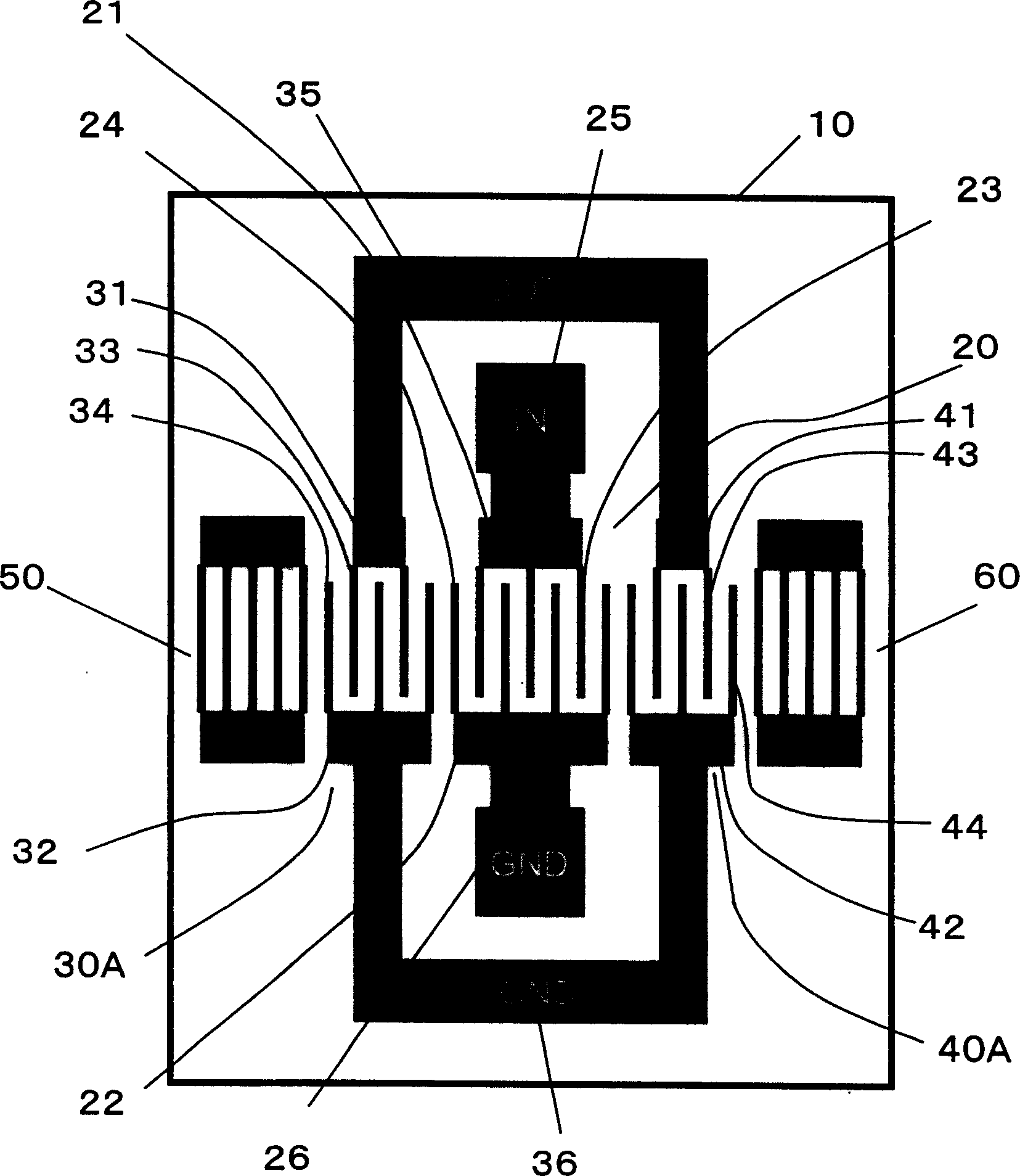
[0055] image 3 is a plan view of the multimode SAW filter device according to the first embodiment of the present invention. exist image 3 In , the same elements as those in FIG. 1 are denoted by the same reference numerals. The multimode SAW filter is a DMS filter having an input IDT 20 and output IDTs 30A and 40A. The reflectors 50 and 60 are disposed outside the output IDTs 30A and 40A, and include a plurality of grid-shaped electrodes formed on the piezoelectric substrate 10 . In this embodiment, ground fingers 24 of input IDT 20 extend in the same direction as ground fingers 34 and 44 of output IDTs 30A and 40A. In other words, the signal electrode fingers 23 of the input IDT 20 extend in the same direction as the signal electrode fingers 33 and 43 of the output IDTs 30A and 40A. With this arrangement, the input terminal 25 of the input IDT 20 and the output terminals 35 of the output IDTs 30A and 40A also extend in the same direction and are adjacent to each other. ...
no. 2 example
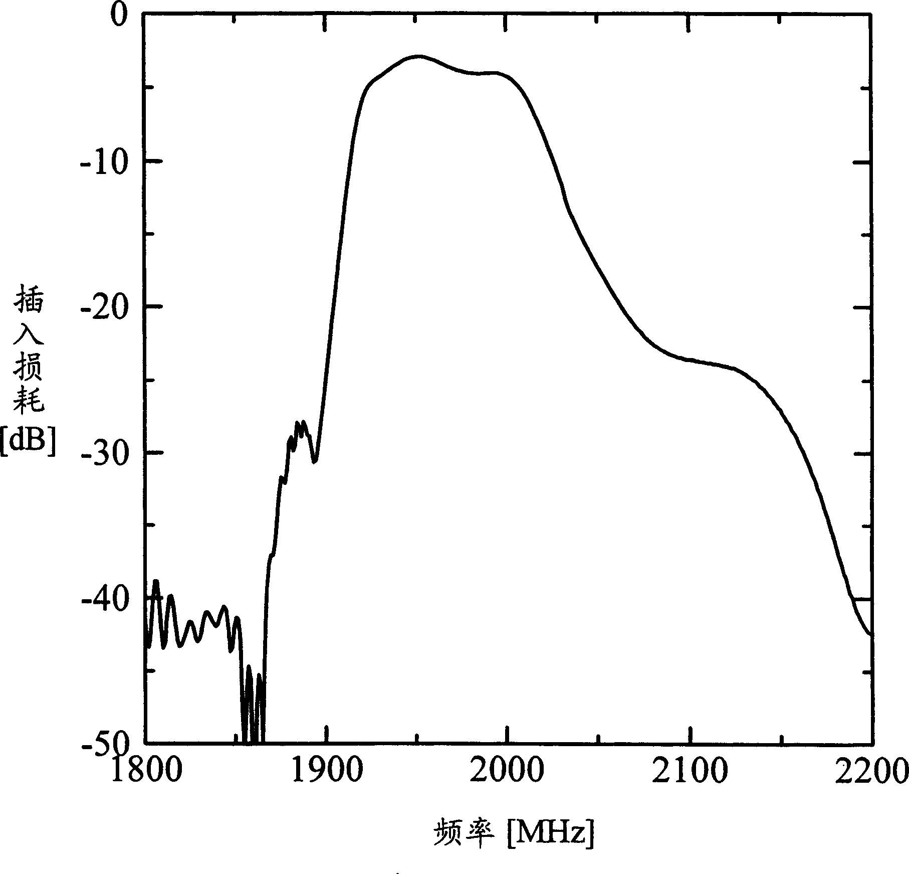
[0065] Next, a second embodiment of the present invention will be described. Compared with the structure in the first embodiment, the second embodiment has a structure that can increase the steepness in the drop-off region of the filter characteristic more, and further reduce the insertion loss. Let's look first at changes in characteristics regarding a structure having an input terminal and an output terminal adjacent to each other, and the window length W of each IDT is changed. The electrode structure used in this experiment was Figure 5 The structure shown in is the same, with a shared ground bus (common ground bus 22A). Figure 12 The experimental results are shown. From these results, it can be found that after the aperture length is reduced, the drop zone of the filter characteristic on the high frequency side moves to the low frequency side, and at the same time the steepness of the drop zone increases. However, when the aperture length becomes smaller, the shape o...
no. 3 example
[0070] Next, a third embodiment of the present invention, of which the filter arrangement of SAW filters connected in parallel is one of the features, will be explained. In the following, a structure with two filters connected in parallel is taken as an example.
[0071] Figure 17 One arrangement is shown that can achieve the smallest possible filter size. Combine the two DMS filters with 100 1 and 100 2 aligned to have the same SAW propagation direction. A common reflector 70 is provided between the two filters 100 1 and 100 2 between. The common reflector 70 acts as the two DMS filters 100 1 and 100 2 public reflector. With this arrangement, the area of one reflector can be saved, so that the size of the filter can be reduced.
[0072] Figure 18 A structure of a SAW filter is shown in which the two DMS filters are arranged to have different SAW propagation paths. The common reflector 70 is divided into two reflectors 70A and 70B. reflector 70A acts as a filt...
PUM
 Abstract
Description
Claims
Application Information