
Pressure device and method

A technology of applying pressure and vacuum pressure, applied in the vacuum pressure device and the pressure field, can solve the problems of large-scale device, large-scale high cost, high cost and so on

Inactive Publication Date: 2004-05-19
SANEI GIKEN
View PDF0 Cites 11 Cited by
  • Summary
  • Abstract
  • Description
  • Claims
  • Application Information

AI Technical Summary

Problems solved by technology

[0024] In addition, when the elastic film is pressurized, the surface of the film embedded in the substrate has unevenness corresponding to the unevenness of the substrate surface. Therefore, the surface of the film must be flattened in the subsequent process. As a result, the configuration of the device or the production line is large. change
[0025] In addition, in order to generate a large pressurization force, it is also conceivable to install the upper and lower pressurization blocks in the cavity without using an elastic film, and to pressurize by driving a motor such as an oil cylinder or a ball screw. The former It is necessary to use oil that may pollute the surrounding environment, and it is necessary to have an installation space for an oil pump, etc. In addition, operations such as piping and gas removal must be performed during the assembly of the device, and parts to prevent oil leakage and oil splash must be prepared, and there is a large size of the device. and high cost issues
In the latter, in order to pressurize with a uniform pressure on the entire pressurized surface, the rigidity of the pressurized block must be increased more than necessary, or a cushioning material must be provided to make the pressure uniform. high cost problem

Method used


Image

  • Pressure device and method
  • Pressure device and method
  • Pressure device and method

Examples


Embodiment Construction

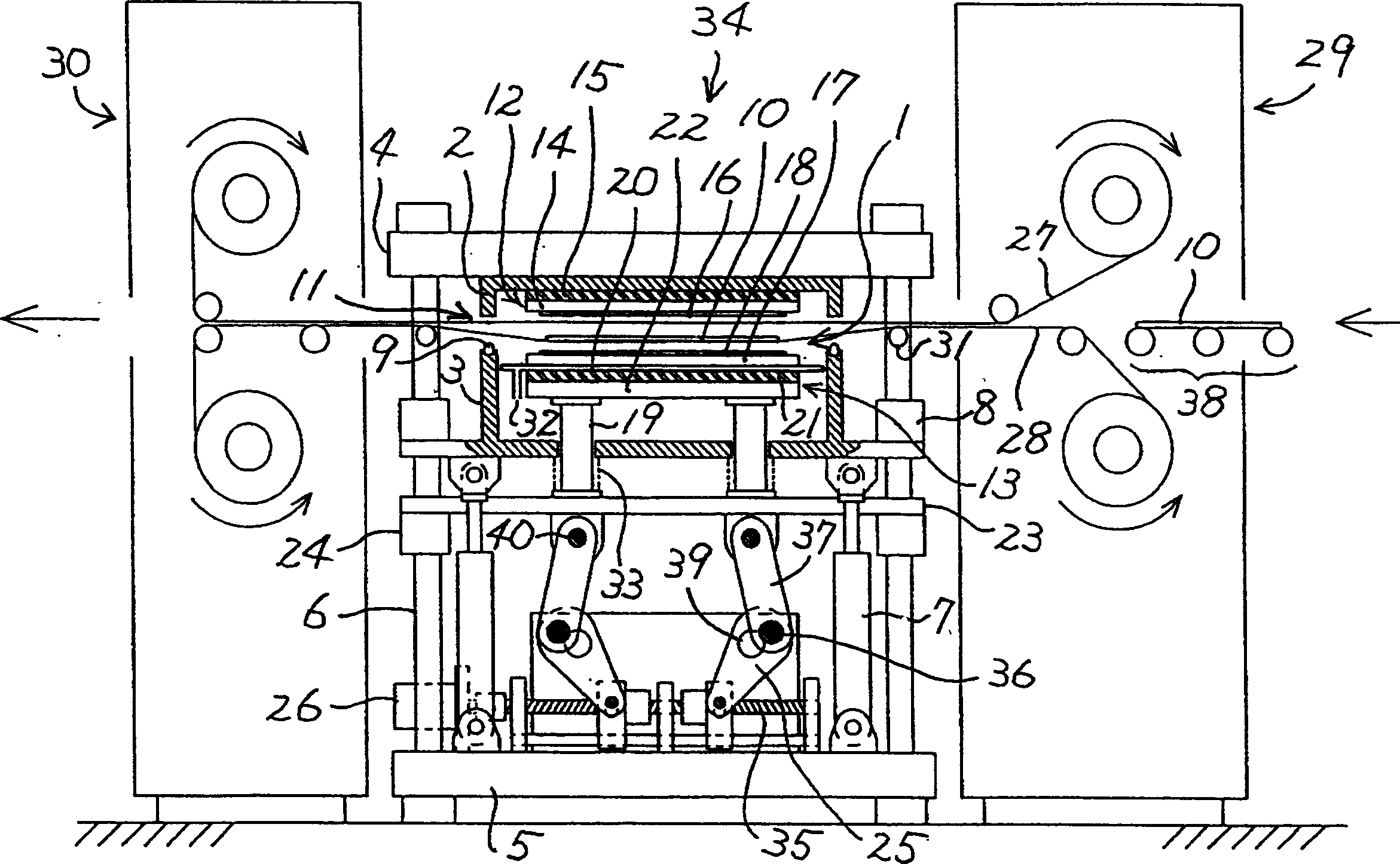
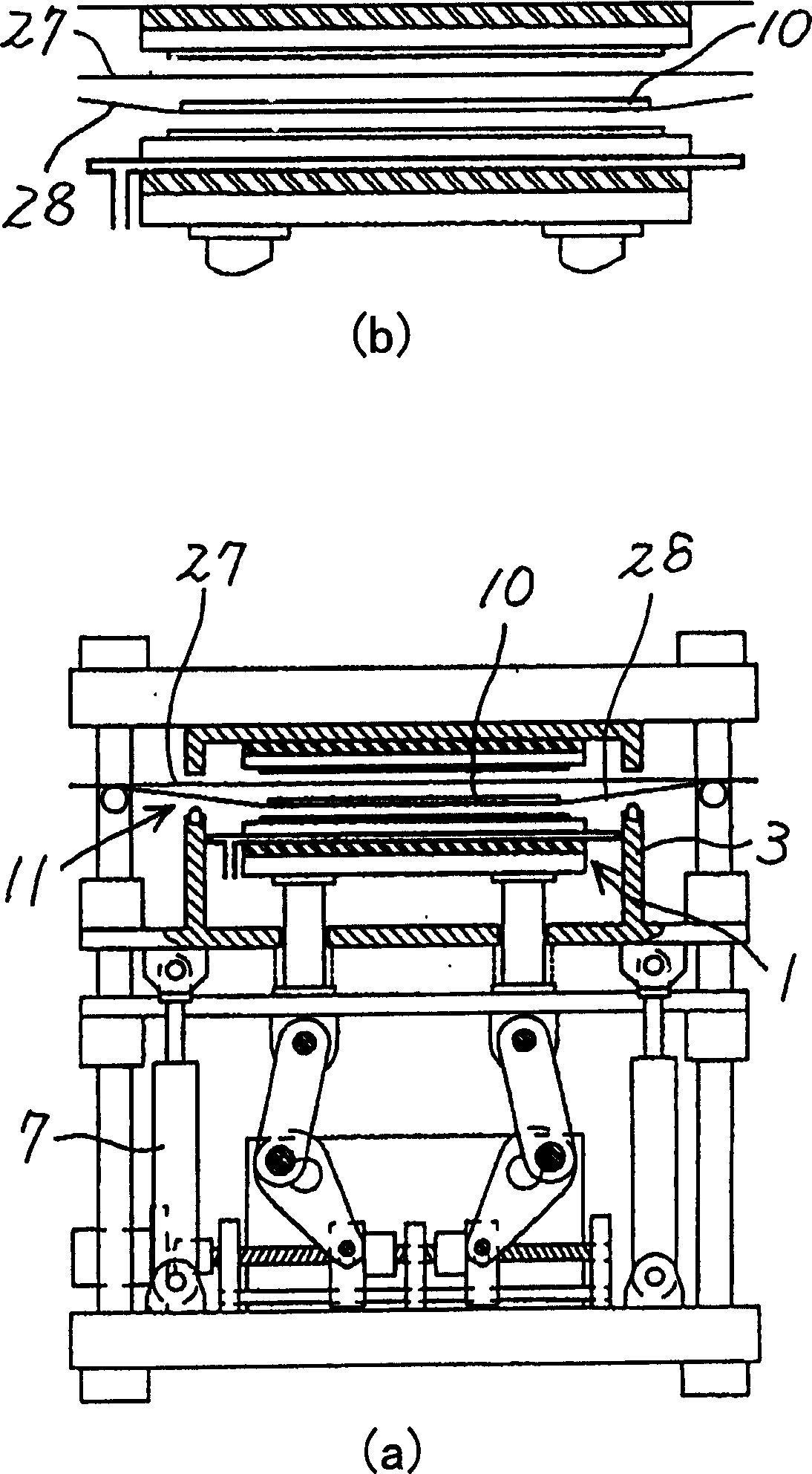
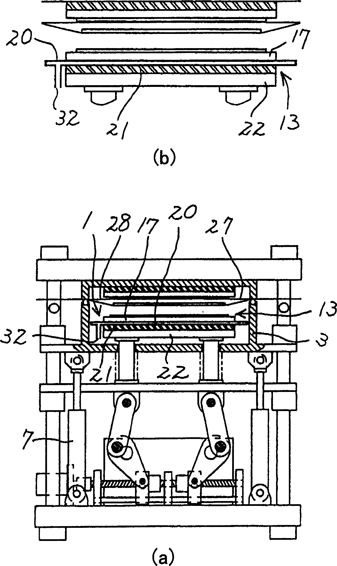
[0042] figure 1 It is a partially cutaway side view showing a vacuum pressure device according to an embodiment of the present invention.

[0043] The vacuum chamber 1 is provided on the vacuum pressure part 34 of the vacuum pressure device. The vacuum chamber 1 is composed of an upper case member 2 and a lower case member 3 .

[0044] The upper housing part 2 is mounted on a support block 4 . In addition, a lower support member 5 as a base is provided on the vacuum pressure part 34, and the support block 4 and the lower support member 5 are connected to each other by a pillar 6 whose upper end is fixed on the support block 4 and whose lower end is fixed on the lower support member 5. connect.

[0045] On the lower surface of the lower case member 3 which is the other member forming the vacuum chamber 1, a driving device 7 such as an air cylinder device is pivotally connected. Furthermore, a guide mechanism 8 for reliably moving the lower case member 3 up and down along th...


PUM


Abstract

A pressing apparatus for flattening a material of a film state on a substrate and a pressing method thereof are provided to bury easily the material of the film state by using a pressing block and an additional driver. A pressing apparatus includes a vacuum pressing unit, a vacuum chamber, a substrate carrier unit, top and bottom pressing blocks, and a first driver. The vacuum chamber(1) is installed at the vacuum pressing unit and includes top and bottom housing members(2,3) for forming a decompressing state and an opening(11) for substrate exit. The substrate carrier unit carries a substrate(10) from or into the vacuum chamber through the opening and includes a couple of film belts(27,28). The top and the bottom pressing blocks(12,13) are arranged in the inside of the vacuum chamber in order to pinch, heat, and press the substrate. The first driver is used for approaching the top and the bottom pressing blocks to each other or separating the top pressing block from the bottom pressing block. The first driver includes a predetermined instrument for forming a reinforced structure to support the repulsive force against the pressure applied to the substrate.

Description

technical field [0001] The present invention relates to a pressure device, especially a vacuum pressure device and a pressure method, for laminating and embedding a thin film material on a substrate or flattening a thin film material on a substrate by heating and pressing. Background technique [0002] On printed circuit boards, irregularities or holes are generated on the surface due to the formation of conductive patterns or the like. When sticking film-like materials such as film-like insulating materials and photosensitive materials on the surface of such a substrate, if a common laminator (laminator) is used, air bubbles are likely to remain in the recesses or holes on the surface of the substrate, Many defective products are produced. [0003] Therefore, a vacuum pressure device is used that sticks a thin film material on the substrate surface in a vacuum. [0004] The film-like material is held on the substrate surface by light pressure before applying the vacuum pr...

Claims


Application Information

Patent Timeline
Patent Type & Authority Applications(China)
IPC IPC(8): H05K3/00H05K3/28
Inventor 三宅健
Owner SANEI GIKEN
Learn More