Device management method

A technology for equipment and management servers, applied in data processing applications, electrical digital data processing, transmission systems, etc., can solve problems such as inquiry obstacles, increased operation status inquiries, and obstacles to printing job transmission, so as to suppress transmission frequency and eliminate errors , the effect of improving the accuracy

Inactive Publication Date: 2004-06-16
SEIKO EPSON CORP
View PDF0 Cites 15 Cited by
  • Summary
  • Abstract
  • Description
  • Claims
  • Application Information

AI Technical Summary

Problems solved by technology

First, in a large-scale printing system, there may be cases where a firewall (fire wall) is installed between the printer to be managed and the management server, thereby preventing the management server from inquiring about the printer.
[0009] Second, if the printer to be managed becomes large, there will be an increase in operational status inquiries and notification tasks, which may hinder the transmission of original print jobs.
[0010] Third, in the network configuration in which the DHCP server dynamically assigns the IP address of each printer, it becomes difficult to specify the printer to be managed
Therefore, reducing the frequency of acquisition of the operating status will reduce the accuracy of the remaining toner amount.

Method used


Image

  • Device management method
  • Device management method
  • Device management method

Examples


Embodiment 1

[0054] A1. System configuration

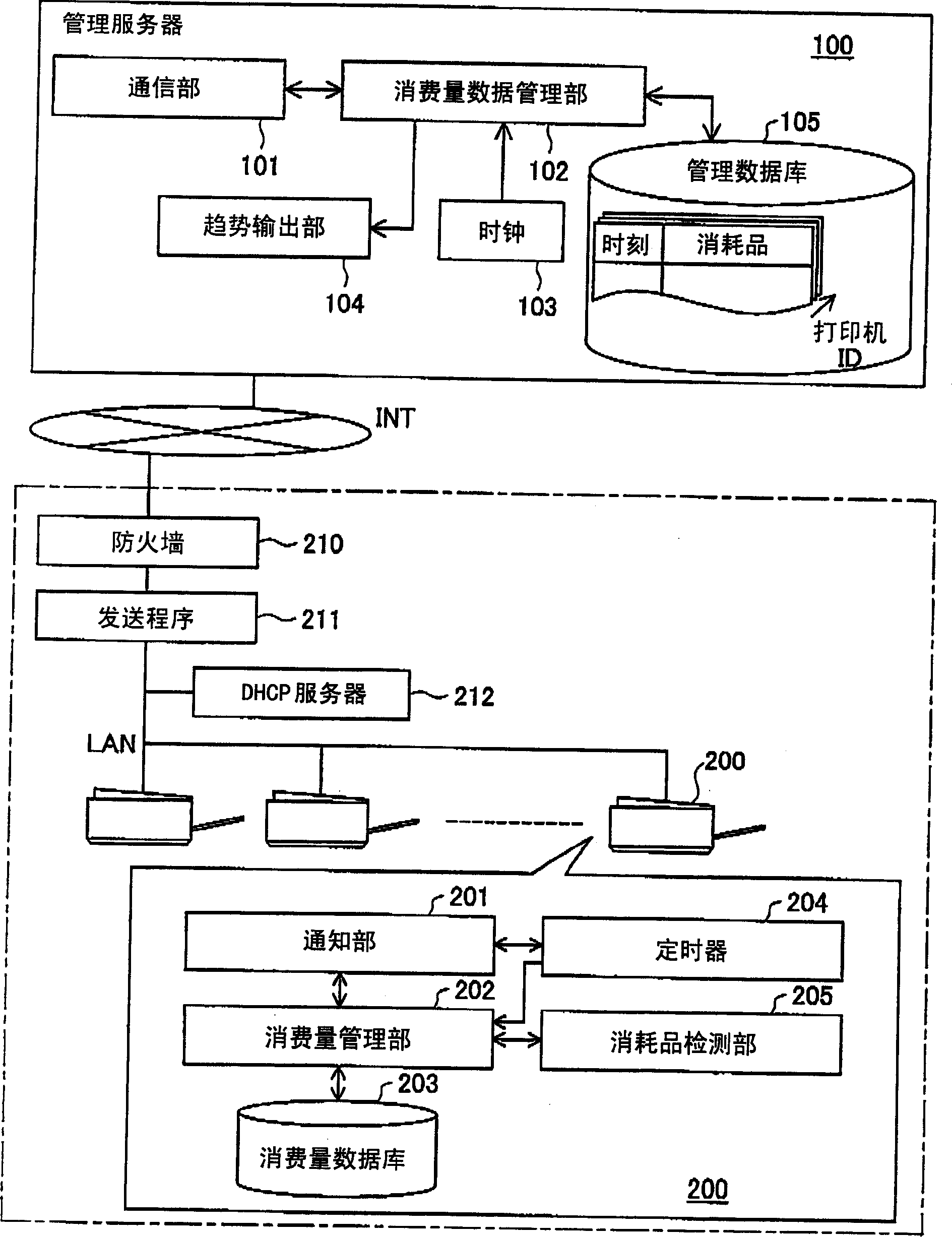
[0055] figure 1 It is an explanatory diagram showing the general configuration of the printing system as the first embodiment. The frame indicated by the dotted line in the figure shows the printing environment constructed in the enterprise. In this printing environment, a plurality of printers including the printer 200 are connected to the local area network LAN. Clients who send print jobs to these printers are also connected to the LAN, but the illustration is omitted.

[0056] The IP address of each printer in the LAN is not fixed but is assigned dynamically by the DHCP server 212 when the power is turned on. The LAN is connected to the network INT through a router 211 and a firewall 210 . Firewall 210 can be set to restrict the passage of packets from the network INT side to the LAN and allow the passage of packets from the LAN side to the network side according to the protocol, for example.

[0057] The management server 100 is conn...

Embodiment 2

[0096] In the first embodiment, the case where the log is recorded after the time is corrected on the printer side is exemplified. In Embodiment 2, an example of a case where the management server performs correction is given. The system configuration is the same as that of Embodiment 1. In the second embodiment, the contents of the processing related to the recording of the log on the printer and the storage of the log on the management server are different from those in the first embodiment.

[0097] 5 is a flowchart of log management processing in the second embodiment. The left side shows the processing repeatedly executed by the control unit of the printer, and the right side shows the processing executed by the management server.

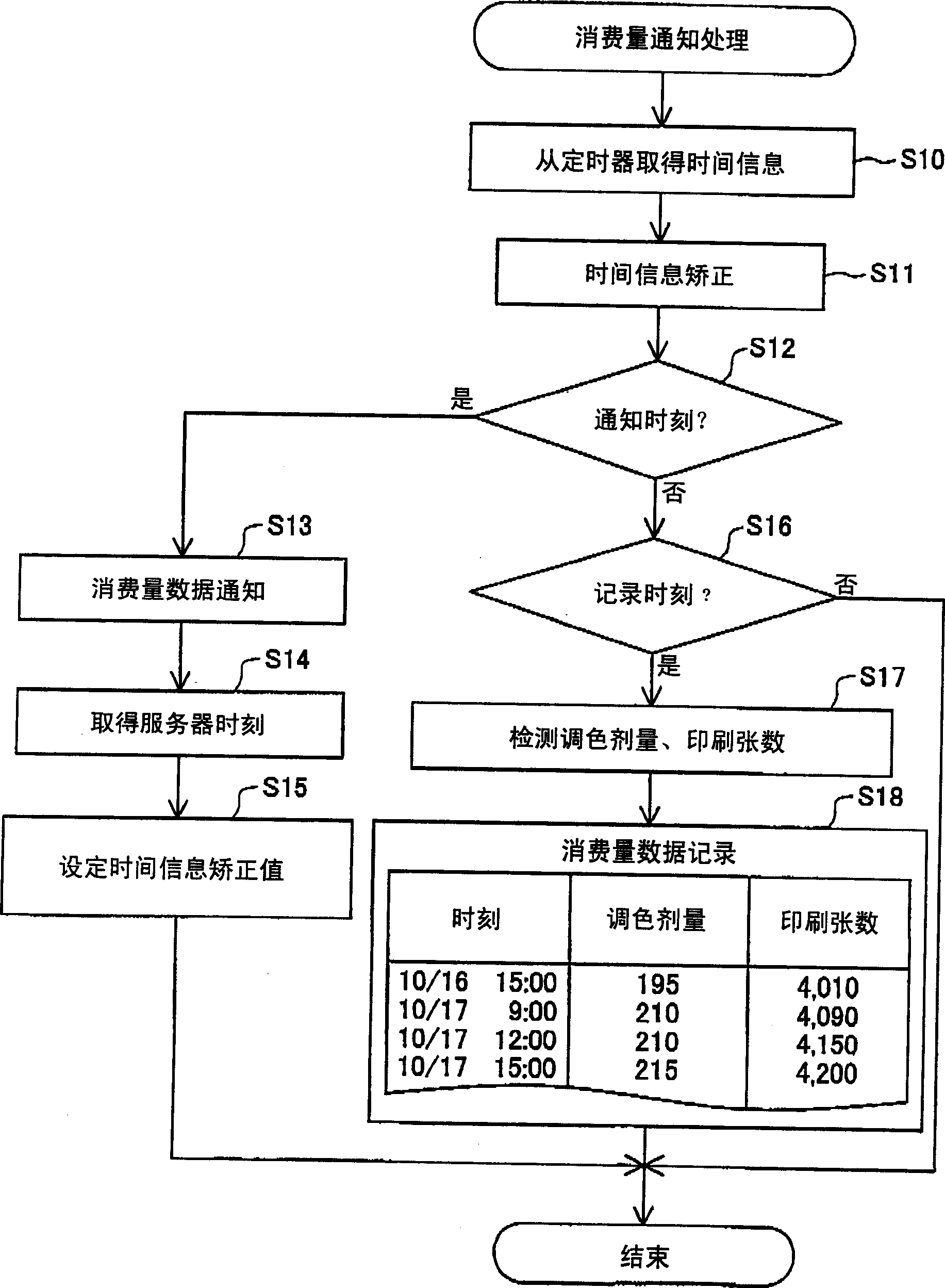
[0098] In the printer, the control unit first obtains the time information from the timer (step S40), and judges whether it is the notification time of the operation record and the recording time of the operation record (step S41, step S42)....

Embodiment 3

[0110] Embodiment 3 shows an example in which when a printer receives a printing file, it receives information on the last update date and time of the printing file and uses the last update date and time as the absolute time.

[0111] Figure 7 A block diagram showing the overall configuration of the printing system 510 of this embodiment. like this Figure 7 As shown, the printing system 510 of this embodiment is configured by connecting a client 520 , an FTP (File Transfer Protocol) server 530 , and a printer 540 via a network 550 .

[0112] One or more clients 520 are connected to this network 550 . The client 520 is constituted by, for example, a terminal for creating numbers for printing such as a personal computer or a PDA (Personal Digital Assistant). In this embodiment, the client 520 creates a print job for the printer 540 based on the printing data created by the user, and transmits it to the FTP server 530 as a printing file by FTP.

[0113] The FTP server 530 i...


PUM


Abstract

A printing system is constructed by connecting a management server with a large number of printers via a network. Each printer records a log, which represents a consumption of an expendable, for example, a consumption of toner, and is mapped to an elapsed time period measured by a built-in timer, and uploads the recorded log to the management server at a preset cycle. The printer acquires an upload time from the management server in the process of uploading and carries out subsequent recording with the acquired upload time as a base time. The printer corrects the elapsed time period mapped to the log, based on the upload time acquired from the management server. This arrangement enables even a printer without a real time clock to prevent expansion of an error and efficiently record the log with high accuracy.

Description

technical field [0001] The invention relates to the technology of remote management of devices connected to a network. Background technique [0002] In recent years, a printing system that connects multiple printers to the network and shared by multiple customers has become popular. In the related printing system, a management server is installed on the network to remotely manage the operation status of each printer. In such a management method, the management server inquires the printer about the operating status information such as the remaining amount of consumables, or the printer periodically notifies the server to manage the operating status. In order to perform such management, it is required to acquire the temporal change of the operation status. [0003] Now, in order to suppress the product cost, some printers do not have a real-time clock inside. This is because when a real-time clock is installed inside, it is necessary to install a battery at the same time so...

Claims


Application Information

Patent Timeline
Patent Type & Authority Applications(China)
IPC IPC(8): G06F3/12G06Q50/00G06Q50/10H04L12/24H04Q9/00
CPCH04L43/067H04L43/0817H04L69/28
Inventor 岛敏博
Owner SEIKO EPSON CORP
Why Eureka
Try Eureka