Noise controlling method via rotation speed of fan

A technology of fan speed and noise value, used in measuring devices, instruments, non-variable-capacity pumps, etc., can solve the problems of spending a lot of manpower and time, adjusting the fan slowly, and having no clear method.

Inactive Publication Date: 2004-06-23
王银霞
View PDF0 Cites 17 Cited by
  • Summary
  • Abstract
  • Description
  • Claims
  • Application Information

AI Technical Summary

Problems solved by technology

As far as the fan with fixed speed is concerned, the noise generated by it is fixed. Therefore, if consumers feel that the noise generated by the fan is too high, they can only replace the fan
As for another variable speed fan, there is no clear method for setting the parameters of the fan speed control. The only way is to slow

Method used


Image

  • Noise controlling method via rotation speed of fan
  • Noise controlling method via rotation speed of fan
  • Noise controlling method via rotation speed of fan

Examples


Embodiment Construction

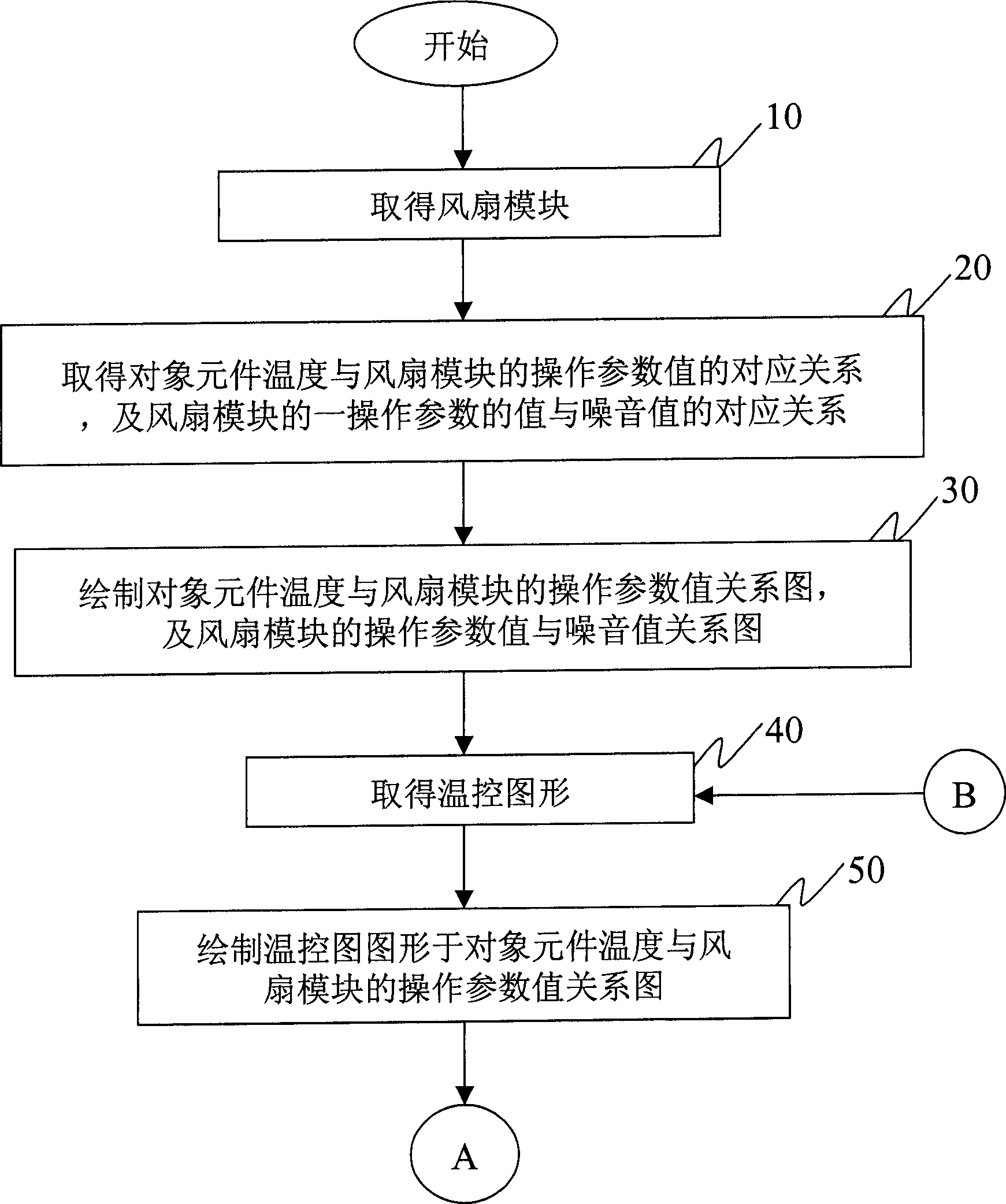
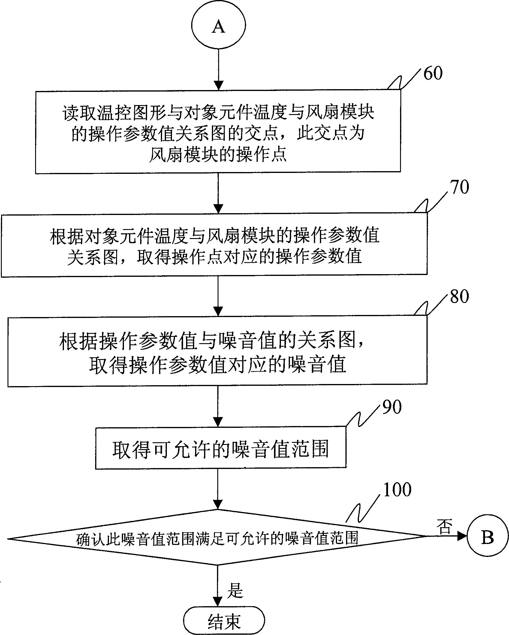
[0018] According to the fan speed control noise value method disclosed in the present invention, the fan speed can be estimated, the noise value of the fan and the temperature of the corresponding CPU can be clearly predicted, and the optimal design of the fan cooling effect and noise value can be obtained, This method reduces a lot of manpower and time required to arrive at the proper rotational speed in the previous try and error method. For a flowchart of this method, please refer to Figure 1A and Figure 1B As shown in the figure:

[0019] First, as Figure 1A As shown, a fan module is obtained (step 10 ). The fan module can be a fan in a personal computer or a notebook computer.

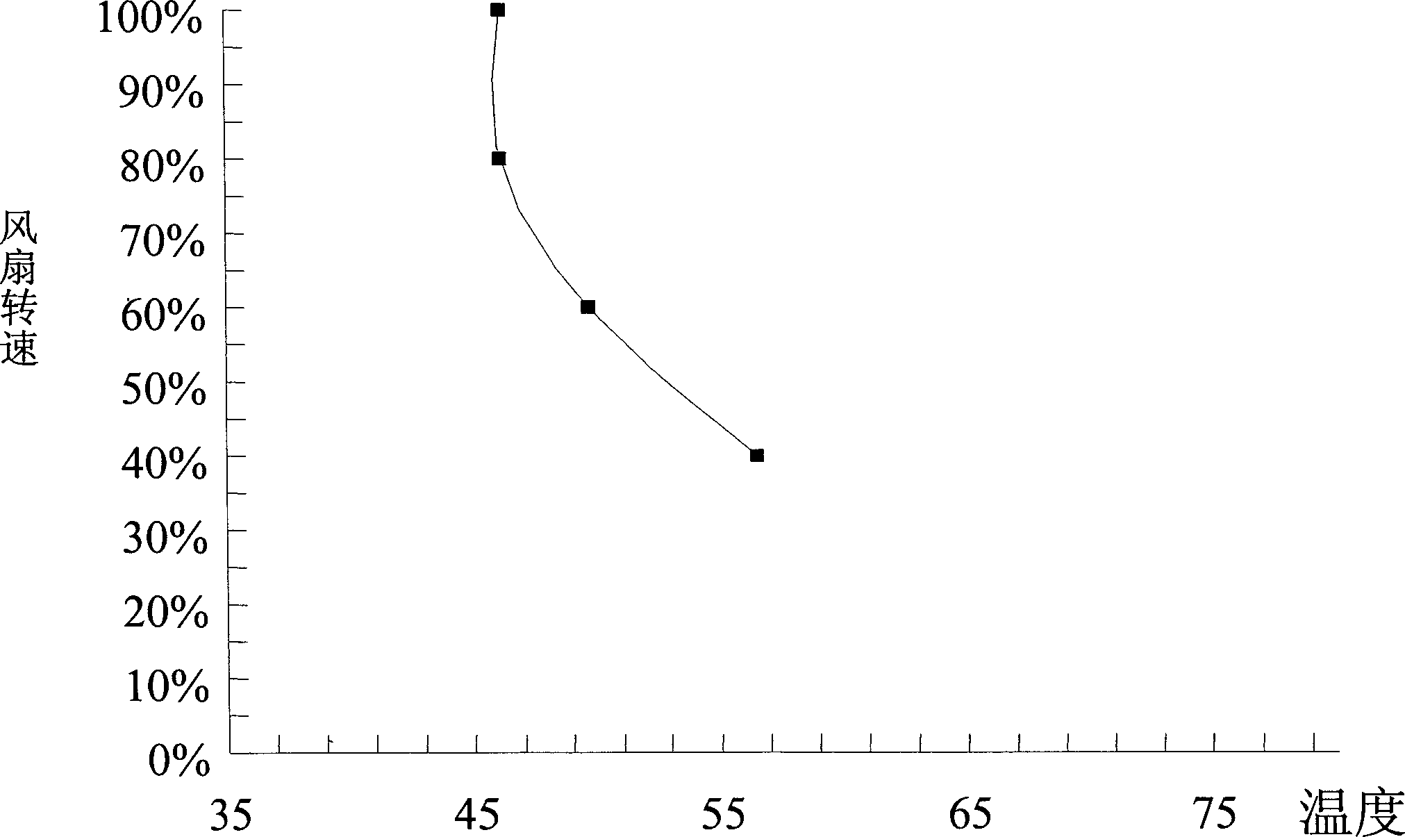
[0020] Next, the corresponding relationship between the temperature of the target component and the operating parameter value of the fan module, and the corresponding relationship between the operating parameter value of the fan module and the noise value are obtained (step 20). Since the most...


PUM


Abstract

The present invention is the fan noise controlling method via rotation speed. The method includes setting one temperature control pattern for predicting fan rotation speed, predicting fan noise and corresponding CPU temperature change, and obtaining the optimized design of the heat radiation effect and noise of the fan. The said method is superior to available try and error method, which needs great amount of man power and time in finding out proper rotation speed.

Description

technical field [0001] The present invention relates to a method for controlling the noise value of the fan speed, in particular to a method for estimating the fan noise value by setting a temperature control graph. Background technique [0002] Since the era of the Pentium, the operating frequency of the central processing unit (CPU) has risen in a straight line, from the original 133MHz to the fastest 2.5GHz, which has only gone through a few years. Although the current mainstream CPUs use 0.18-micron or even 0.13-micron manufacturing technology, because the high-speed CPU is composed of many transistors, its heat generation is much higher than that of the previous CPU. Nowadays, almost all CPUs above 1GHz have a power of more than 40W, and the power consumption of Pentium 4 CPUs above 2GHz is as high as 70W. Such high power consumption directly leads to a surge in the heat generation of the CPU. Especially in summer, if good heat dissipation measures are not taken, the l...

Claims


Application Information

Patent Timeline
IPC IPC(8): F04D25/08G01D21/02G06F1/20
Inventor 曾翌维
Owner 王银霞
Why Eureka
Try Eureka