Scanning method of forming planar light source, planar light source and laser projection television

A scanning method and surface light source technology, applied in the direction of TV, color TV, color TV components, etc., can solve the problems of beam coherence and uneven brightness, etc.

Active Publication Date: 2004-06-23
JILIN OPTOELECTRONICS ENTERPRISE INCUBATOR
View PDF0 Cites 32 Cited by
  • Summary
  • Abstract
  • Description
  • Claims
  • Application Information

AI Technical Summary

Problems solved by technology

[0010] In order to overcome the problems of coherence and uneven brightness of the light beam in the laser display mode, the present invention adopts the scanning method to reali

Method used


Image

  • Scanning method of forming planar light source, planar light source and laser projection television
  • Scanning method of forming planar light source, planar light source and laser projection television
  • Scanning method of forming planar light source, planar light source and laser projection television

Examples


no. 1 example

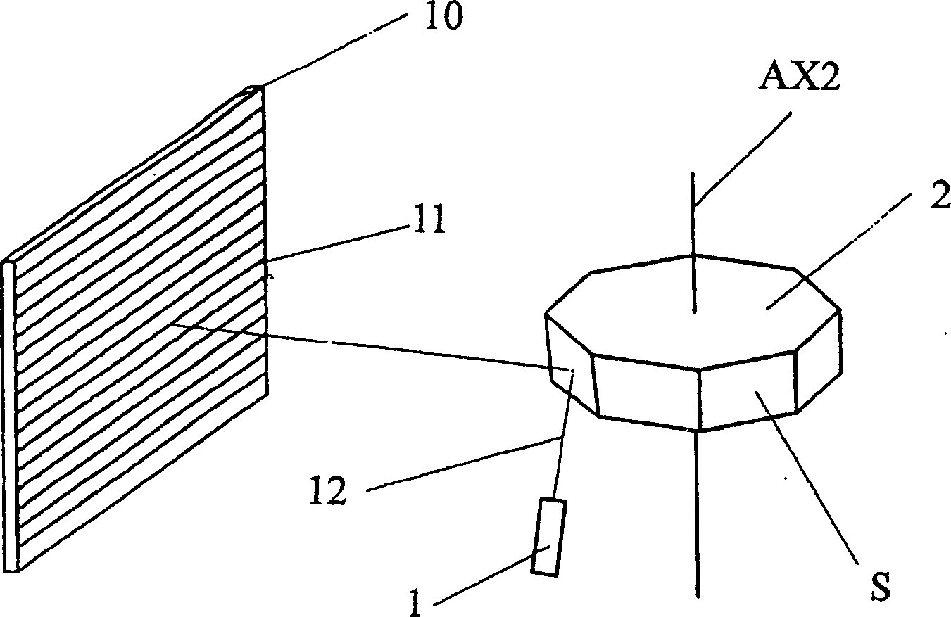
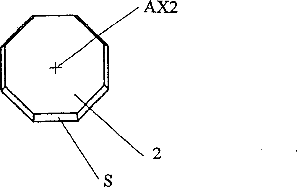
[0036] figure 1 It shows a principle diagram of realizing two-dimensional scanning by using a single mirror and multiple planes with variable inclination angles according to the first embodiment of the present invention. Such as figure 1 As shown, a scanning surface light source used in laser video display, including a laser (1) and a rotating mirror (2), is characterized in that the laser beam (12) emitted by the laser (1) irradiates a multi-faceted rotating The rotating mirror (2), each reflecting surface (S) of the multi-faceted rotating mirror (2) is deflected at a certain angle relative to the rotating axis (AX2), each surface makes the reflected light beam scan into a straight line (11), and each time a surface is rotated, The scanning line is translated by one line, and the scanning plane is formed by sequential translation of the scanning line. The high-speed rotating polygonal mirror (2) is a symmetrical polygon centered on the axis (AX2), each side is a mirror su...

no. 2 example

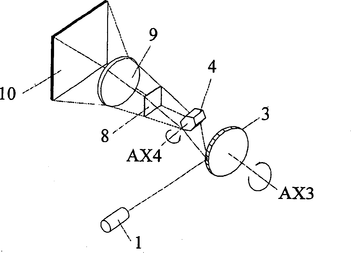
[0041] Such as image 3 Shown is a schematic diagram of the second embodiment of the present invention using a line scanning rotating mirror and adding a field scanning rotating mirror to realize two-dimensional scanning.

[0042] Such as image 3 As shown, the laser 1 emits a laser beam, which is incident on the line scanning rotating mirror 3, and the line scanning rotating mirror 3 rotates around the rotation axis AX3 to scan the laser beam into a line and project it on the field scanning rotating mirror 4, and the field scanning rotating mirror 4 rotates The rotating shaft AX4 rotates to make the laser beam form a two-dimensional scanning surface, which is irradiated on the area array spatial light modulator 8, and then the image of the area array spatial light modulator is projected onto the screen 10 by the lens 9, realizing the illumination by the scanning area light source The laser image is obtained by the area array spatial light modulator.

no. 3 example

[0044] Such as Figure 4 Shown is a schematic diagram of the third embodiment of the present invention using a line scanning rotating mirror and adding a field scanning vibrating mirror to realize two-dimensional scanning.

[0045] Such as Figure 4 As shown, the laser 1 emits a laser beam, which is incident on the line scanning rotating mirror 3, and the line scanning rotating mirror 3 rotates around the rotation axis AX3 to scan the laser beam into a line and project it on the field scanning galvanometer 5, and the field scanning galvanometer 5 revolves The rotating shaft AX5 swings back and forth, so that the laser beam forms a two-dimensional scanning surface, which is irradiated on the area array spatial light modulator 8, and then the image of the area array spatial light modulator is projected onto the screen 10 by the lens 9, realizing the scanning surface The light source illuminates the area array spatial light modulator to obtain the laser image.


PUM


Abstract

The present invention proposes scanning method to form planar light source, the scanning planar light source and projection television with the planar light source. The method is that a fine light beam is projected onto a multiple-surface reflector in high speed rotation, the rotation reflector has fixed inclination angle in the rotation shaft direction in its reflecting surfaces and thus the scanning light beam forms planar scanning in the irradiated plane. By means of scanning, the planar array spatial light modulator for light display obtains homogeneous irradiation with high light energy utilization, homogeneous illumination and no interference. The scanning features that each scanning dot can cover one large pixel and the scanning lines have relatively more overlapping to ensure homogeneous brightness of the scanned plane.

Description

technical field [0001] The invention belongs to the field of laser and laser video display, and relates to laser beam expansion and light scanning technology capable of eliminating laser interference, in particular to a scanning type laser beam display with uniform brightness, no interference, and high light energy utilization rate that can be used in laser video display. surface light source. Background technique [0002] Since the 1990s, with the continuous development of high technology, TV display technology has also been continuously introduced, and color TV display technology has been researched internationally. For example, LCD TV display technology, rear projection TV display technology, plasma TV display technology, laser color TV display technology, stacked LED TV display technology and so on. These types of TV display technologies have their own advantages and disadvantages. There are two kinds of existing TV display technologies closest to the present invention....

Claims


Application Information

Patent Timeline
IPC IPC(8): G02B26/10G02B26/12G02B27/00G02F1/00H04N5/00
Inventor 刘伟奇
Owner JILIN OPTOELECTRONICS ENTERPRISE INCUBATOR
Why Eureka
Try Eureka