
Light board

A light guide plate and optical technology, which is applied in the field of light guide plates, can solve the problems of limited light scattering ability, uneven light, and difficult upward emission of light, etc., to achieve the effect of enhancing light scattering ability and improving uniformity

Inactive Publication Date: 2004-06-30
HONG FU JIN PRECISION IND (SHENZHEN) CO LTD +1
View PDF0 Cites 7 Cited by
  • Summary
  • Abstract
  • Description
  • Claims
  • Application Information

AI Technical Summary

Problems solved by technology

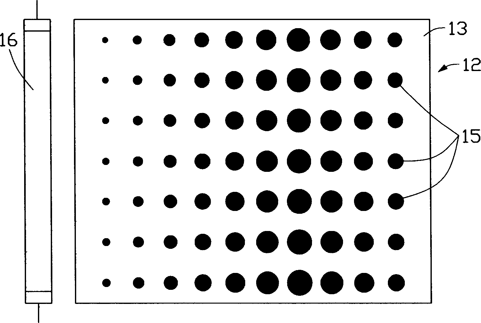
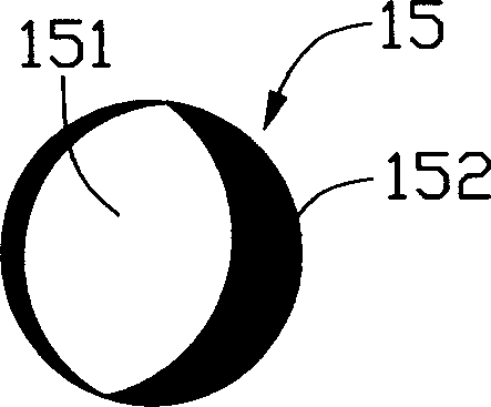
[0007] image 3 for figure 1 The schematic diagram of the optical effect of the reflective dots 15 is shown. The entire reflective dot area has obvious and concentratedly distributed brighter areas 151 and darker areas 152, wherein the brighter areas 151 are where the reflective dots 15 can effectively scatter incident light. In the effective reflection part, the darker region 152 is a region with a weaker effect on the incident light, and the darker region 152 accounts for a relatively large proportion, so the light scattering ability provided by the reflective grid point 15 is limited, and the side incident to the reflective grid point The light of 15 is not easy to exit upwards; and the light emitted from the light guide plate 10 is not uniform due to the presence of obvious and concentrated areas with strong light scattering effect and weak light scattering effect at the same time.

Method used


Image

  • Light board
  • Light board
  • Light board

Examples


Embodiment Construction

[0017] see Figure 4 , is a cross-sectional view of the light guide plate 20 of the present invention. The light guide plate 20 includes a light incident surface 21 for receiving incident light, an end surface 22 opposite to the light incident surface 21, a light reflecting surface 23 for reflecting light and intersecting the light incident surface 21, and a light reflecting surface 23 opposite to the light exit surface 24 . Wherein, the light guide plate 20 is wedge-shaped, or may be flat-shaped, and the light-reflecting surface 23 is provided with a plurality of reflective dots 25 for uniformly emitting incident light to the light-emitting surface 24 .

[0018] Please also refer to Figure 5 ,yes Figure 4 A schematic diagram of the fine structure of the reflective dots 25 shown. The reflective dots 25 can be prepared by a UV (Ultraviolet, ultraviolet) substrate or an IR (Infra-red, infrared) substrate, which includes a plurality of silicon dioxide particles 251, wherein...


PUM

PropertyMeasurementUnit
refractive indexaaaaaaaaaa

Abstract

The invention is a kind of light board, which comprises a light entrance face which is used to receive the incoming ray, a end face opposite to the entrance face, a light reflection face for reflected light and intersects with the entrance face, several reflecting mesh spots on the reflection face and a light exit facet opposite to the reflecting face. The mesh spots include several optical scattering particles, which has several light reflecting facets. All the light reflecting facets can reflect the beams from side direction to mesh spots, the side direction light is emitted uprightly.

Description

【Technical field】 [0001] The invention relates to a light guide plate, in particular to a light guide plate applied to a liquid crystal display. 【Background technique】 [0002] In recent years, with the development of various information, communication, and consumer liquid crystal display products, especially the development of various color liquid crystal display products, the requirements for the luminance, light uniformity, and light output efficiency of the light source system are increasing day by day. [0003] The light guide plate is an important component of the liquid crystal display light source system. It generally includes a light incident surface, a light exit surface, and a light reflection surface. According to the process principle, it is mainly divided into two types: printed (Screen Printing) light guide plate and non-printed light guide plate , the production material is generally PMMA (Polymethmethacrylate, polymethyl methacrylate), and the refractive ind...

Claims


Application Information

Patent Timeline
Patent Type & Authority Applications(China)
IPC IPC(8): G02B5/02G02F1/13357
Inventor 吕昌岳林明辉刘铭萱陈杰良余泰成
Owner HONG FU JIN PRECISION IND (SHENZHEN) CO LTD
Learn More