
A flexible linear light emitting element and a method of producing the same

a light emitting element and flexible technology, applied in the direction of instruments, cladded optical fibers, fibre light guides, etc., can solve the problems of limited application scope, achieve the effect of improving the luminance of the element, enhancing the light scattering effect, and largely improving the light emitting performan

Active Publication Date: 2018-08-16
FUKUBI KAGAKU IND
View PDF1 Cites 1 Cited by
  • Summary
  • Abstract
  • Description
  • Claims
  • Application Information

AI Technical Summary

Benefits of technology

The present invention solves the problem of flexibility by providing an optical fiber type linear light emitting element that is flexible enough to be bent to a large extent and fixed on an object. It also improves the luminance of the element by enhancing the light scattering effect within the cored layer. Furthermore, the flexible linear light emitting element provides improved light emitting performance with the aid of the chemical action of the acrylic thermoplastic elastomer from which the cored layer is made. This makes it highly useful for practical applications.

Problems solved by technology

Therefore, the application is limited in scope.

Method used

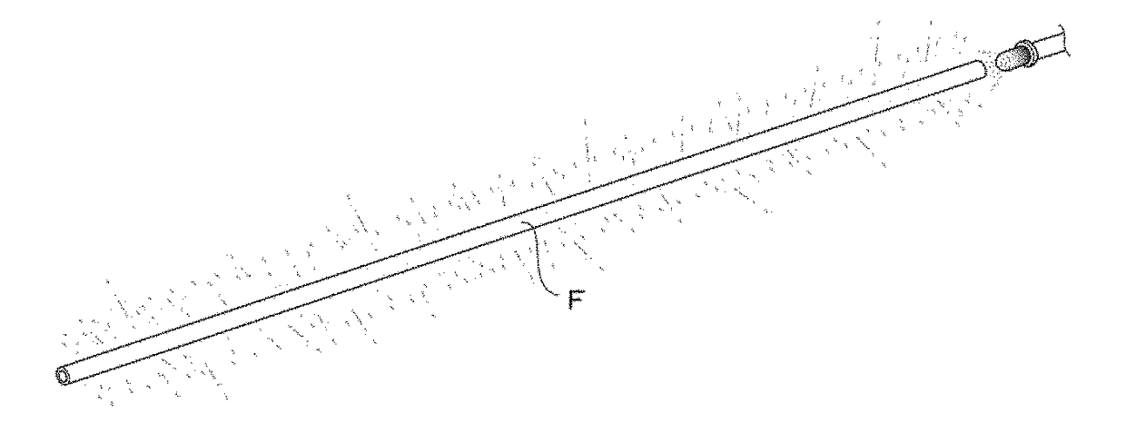
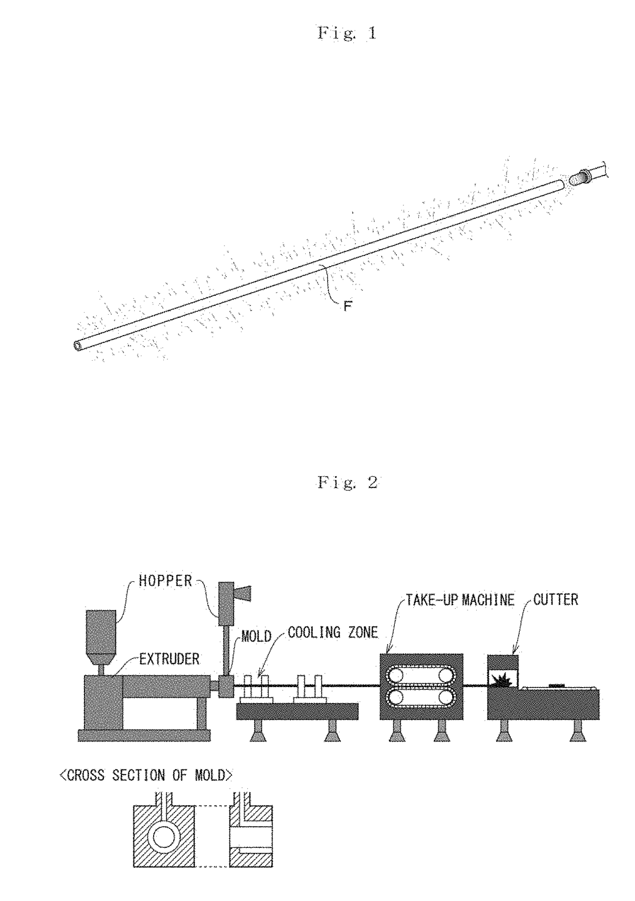

Image

  • A flexible linear light emitting element and a method of producing the same
  • A flexible linear light emitting element and a method of producing the same
  • A flexible linear light emitting element and a method of producing the same

Examples


examples

[0036](Verification Test of Advantageous Effect)

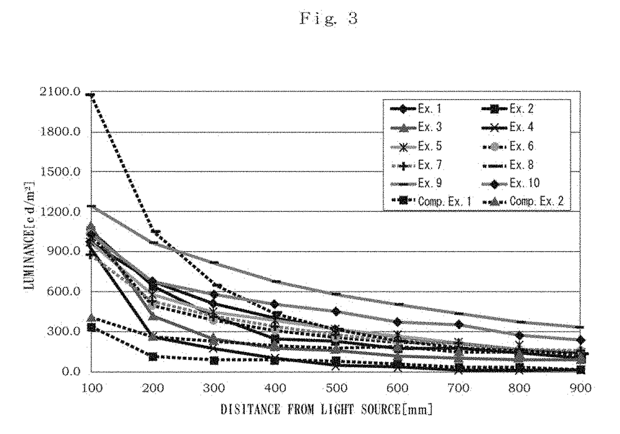
[0037]The verification test of the present advantageous effects is explained as follows. In the first place, multiple samples which are different in production conditions from one another (a material of the cored layer and the clad layer respectively, a thickness of the clad layer, compounding a colorant into the clad layer or not) are prepared; and evaluations on flexibility, light emitting performance (luminance and attenuation rate), appearance and the anti-peeling property of the clad layer against the cored layer are made for the respective samples. The production conditions of the respective samples according to comparison examples 1 and 2 as well as the first to tenth examples are summarized as follows.

first example

[0040]In this example, a linear light emitting element is produced through co-extrusion molding by adopting MMA-BA block copolymer whose MFR under the test conditions of 190 degrees Centigrade in temperature and 2.16 kg in load is 3.1 g / 10 min and whose flexural modulus of elasticity is 400 MPa for the material of the cored layer; and adopting ETFE whose melting point, elongation, flexural modulus of elasticity and MFR under the test conditions of 297 degrees Centigrade in temperature and 5 kg in load are 226 degrees Centigrade, 430%, 810 MPa and 26.4 g / 10 min respectively for the clad layer. The thickness of the clad layer is defined as 0.24 mm, in which 0.065 parts by weight of titanium dioxide acting as a colorant is added against 100 parts by weight of the material of the clad layer.

second example

[0041]In this example, a linear light emitting element is produced through co-extrusion molding by adopting MMA-BA block copolymer whose MFR under the test conditions of 190 degrees Centigrade in temperature and 2.16 kg in load and whose flexural modulus of elasticity is 440 MPA for the material of the cored layer; and adopting ETFE whose melting point, elongation, flexural modulus of elasticity and MFR under the test conditions of 297 degrees Centigrade in temperature and 5 kg in load are 226 degrees Centigrade, 430%, 810 MPa and 26.4 g / 10 min respectively for the clad layer. The thickness of the clad layer is defined as 0.27 mm, in which 0.065 parts by weight of titanium dioxide acting as a colorant is added against 100 parts by weight of the material of the clad layer.


PUM

PropertyMeasurementUnit
temperatureaaaaaaaaaa
Melt Flow Rateaaaaaaaaaa
melting pointaaaaaaaaaa

Abstract

A flexible linear light emitting element to be flexibly bent along the shape of an object to be decorated or to be bent in accordance with a linearly represented decorative letter or decorative pattern of any kind and to excel in light emitting performance such as luminance as well as a method of producing the same. The optical fiber type linear light emitting element includes a bar-shaped extrusion-molded article in which a clad layer made from a fluorine resin is integrally formed over the periphery of a cored layer made from an acrylic thermoplastic elastomer; and a block copolymer of methyl methacrylate and butyl acrylate or a block copolymer of methyl acrylate and butyl acrylate, the flexural modulus of elasticity (according to ASTM D790) of the copolymers ranging from 50 to 500 MPa, is adopted for the material of the cored layer.

Description

TECHNICAL FIELD[0001]The present invention relates to improvement on a linear light emitting element, in detail, pertaining to a flexible linear light emitting element which is flexibly bent along the shape of an object to be decorated or bent in accordance with a linearly represented decorative letter and pattern and is excellent in light emitting performance such as luminance.PRIOR ART[0002]In recent years, a linear light emitting element has been used for a number of optical ornaments such as ornamental fittings or illuminations and decorative signs, in which the neon lamps having been used in the form of a linear light emitting element since before is made of a glass tube poor at flexibility, so that there is no bending the same along the curved portion of a wall or drawing a decorative letter or pattern with the same[0003]In view of the above, such optical fiber type linear light emitting elements molded from plastics are disclosed in Documents 1 and 2 below as allowing the sam...

Claims


Application Information

Patent Timeline
Patent Type & Authority Applications(United States)
IPC IPC(8): G02B6/02F21V8/00G02B6/44
CPCG02B6/02033G02B6/001G02B6/4479B29D11/00663C08L33/02C08L53/00G02B6/02G02B6/00
Inventor KANAMORI, NAOAKI
Owner FUKUBI KAGAKU IND
Learn More