Laser interfere length measuring system with real time compensation for Abbe error

A technology of real-time compensation and laser interference, applied in measuring devices, optical devices, image data processing, etc., can solve problems such as sharp increase in cost, increase in instrument volume, complex structure, etc., and achieve integration, simple structure and principle , the effect of high accuracy

Inactive Publication Date: 2004-07-07
中国航空工业总公司第三〇四研究所
View PDF0 Cites 19 Cited by
  • Summary
  • Abstract
  • Description
  • Claims
  • Application Information

AI Technical Summary

Problems solved by technology

[0016] In order to overcome the disadvantages of the existing Abbe error compensation method that the volume of the instrument increases, the structure is complicated, and the cost increases sharply, the present invention provides a laser interferometric length measur

Method used


Image

  • Laser interfere length measuring system with real time compensation for Abbe error
  • Laser interfere length measuring system with real time compensation for Abbe error
  • Laser interfere length measuring system with real time compensation for Abbe error

Examples


Embodiment Construction

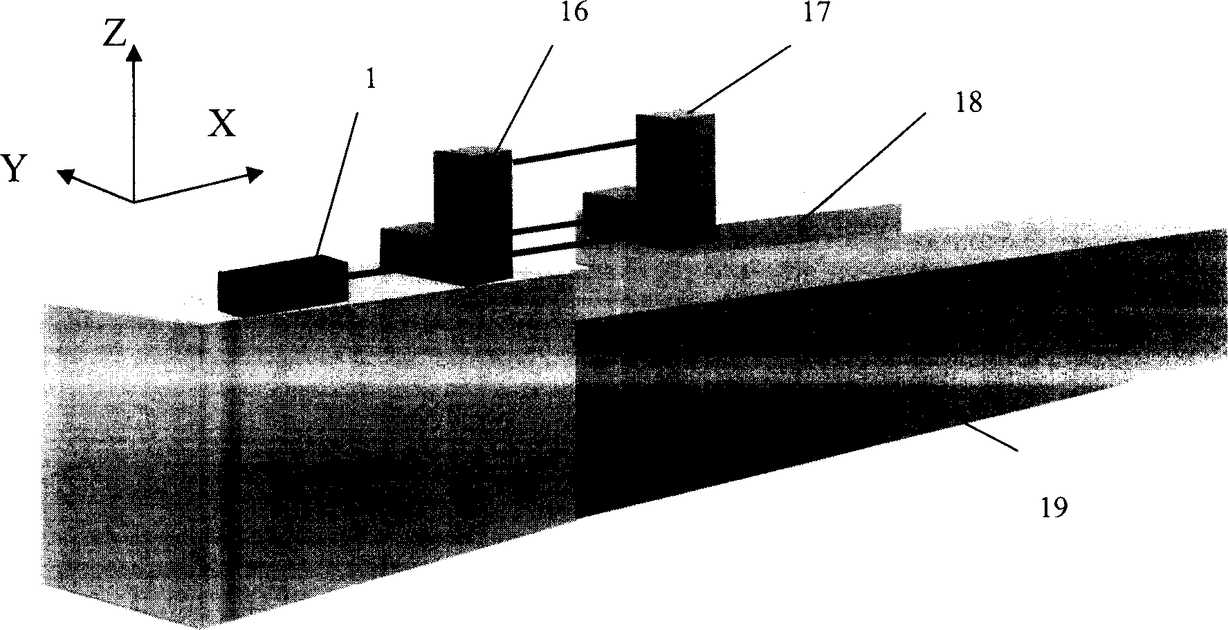
[0032] Figure 5It is a composition system diagram of three-way interference light to realize real-time compensation of Abbe error. The moving directions of the three paths of light are all along the X axis. The laser starts from the HP5527 laser head (1) in the laser (15), and the laser is divided into two beams by a 1 / 3 beam splitter (2), accounting for 1 / 3 of the total energy. A beam of light passes through a 90° beam deflection mirror (3) and an interference mirror (4) and is directed to a corner cube prism (5) on the workbench (the light of this path is in the Z direction). The other beam of light (accounting for 2 / 3 of the total energy) is divided into two beams after passing through the 1 / 2 beam splitter (6), and one of the beams of light passes through the interference mirror (10) and is directly directed to the corner cube prism on the workbench (11) (the light of this path is X direction), and the remaining beam of light passes through the 90-degree beam refracting ...


PUM


Abstract

The length measuring system utilizes a two-frequency laser projector, two beam splitters and two light-beam refractors of 90 degree to carry on length measurement for three pathes of interferometric light simultaneously so that two-dimensional Abbe angle for guide track can be obtained on real time, and thereby real time compensation for Abbe error can be achieved.

Description

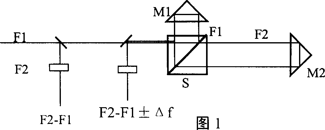
Technical field [0001] The invention relates to a length measuring system using laser interference, in particular to a length measuring system realizing real-time compensation of Abbe errors, belonging to the technical field of precision measurement. Background technique [0002] At present, the most accurate length measurement system in the world should be the laser interferometric length measurement system. The famous product is the dual-frequency laser interferometer of HP Company. It is an instrument that measures the measured length based on the wavelength of the light wave. As shown in Figure 1: the light source is a laser that can emit two frequencies, one frequency is F1, the other frequency is F2, the frequency difference between F1 and F2 is about 1MHz, and they are linear polarizations whose vibration directions are perpendicular to each other Light. A small part of the signal in the light is taken out of the beat frequency to form a reference signal with a frequ...

Claims


Application Information

Patent Timeline
IPC IPC(8): G01B9/02G01B11/02G06T1/00
Inventor 李百源
Owner 中国航空工业总公司第三〇四研究所
Why Eureka
Try Eureka