Human Shaped robot foot and foot force information detecting method

A robot foot and humanoid technology, applied in manipulators, manufacturing tools, etc., can solve problems such as calculation errors, model inaccuracy errors, sensor structures, and measuring ranges that cannot meet the requirements

A robot foot and humanoid technology, applied in manipulators, manufacturing tools, etc., can solve problems such as calculation errors, model inaccuracy errors, sensor structures, and measuring ranges that cannot meet the requirements

CN1513647AInactive Publication Date: 2004-07-21HEFEI INST OF INTELLIGENT MACHINERY CHINESE ACAD OF SCI

Image

  • Human Shaped robot foot and foot force information detecting method
  • Human Shaped robot foot and foot force information detecting method
  • Human Shaped robot foot and foot force information detecting method

Examples


Embodiment Construction

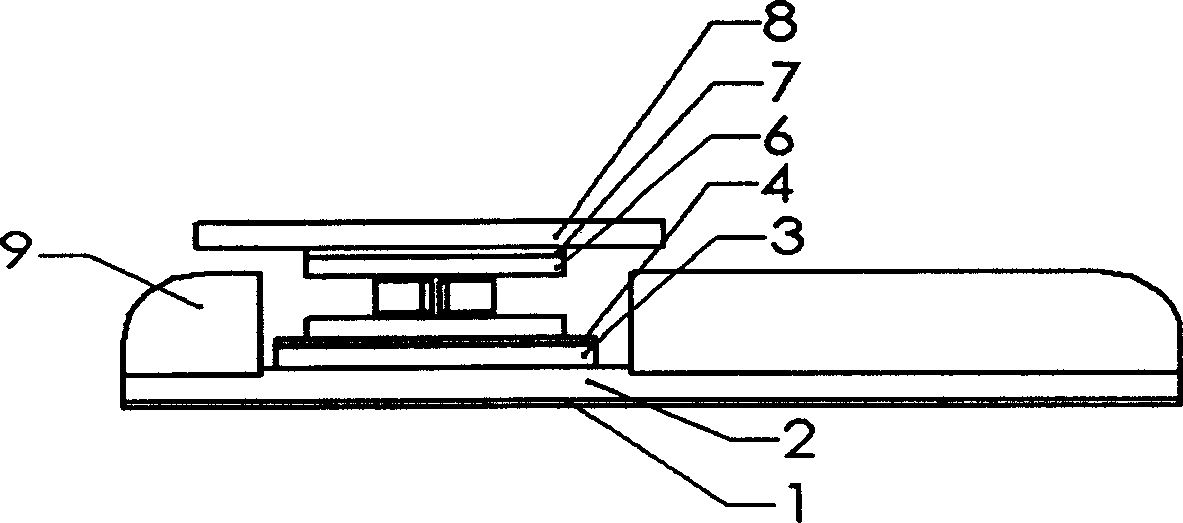
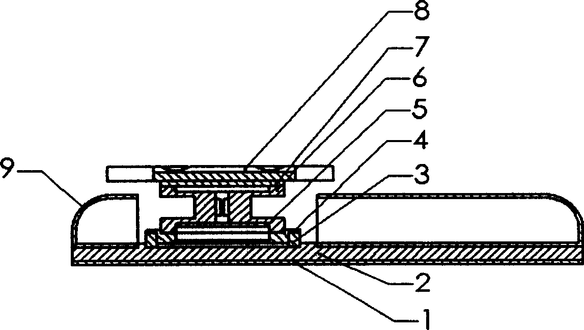
[0047] figure 1 It is the appearance diagram of the foot of the humanoid robot of the present invention, figure 2 It is a schematic diagram of a humanoid robot foot section, which includes a rubber foot layer 1, a foot plate 2, a rubber gasket ring 3, a lower flange 4, a signal processing circuit 5, a six-component force sensor 6, an upper flange 7, an adapter plate 8 and a foot surface 9 .

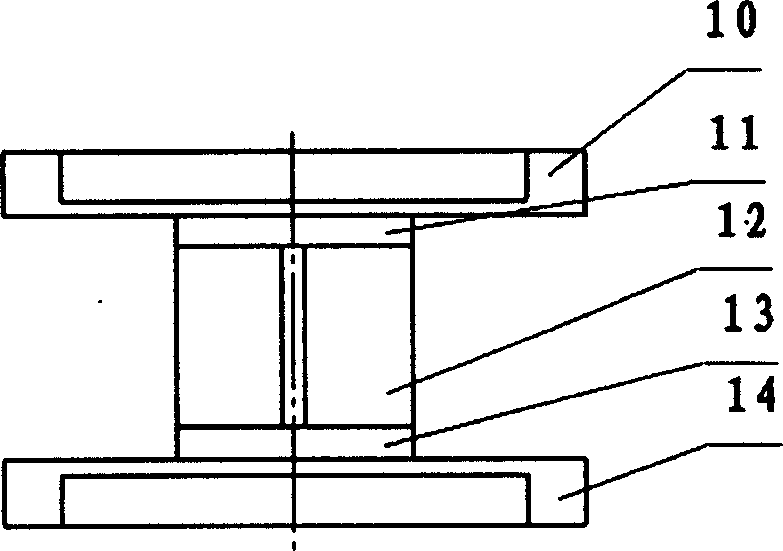
[0048] image 3 It is a schematic diagram of the structure of the foot six-component force sensor, wherein the upper circular diaphragm 10 and the lower circular diaphragm 14 adopt a circular diaphragm structure with a hard center, and the hard center 11 of the upper circular diaphragm 10 and the lower circular diaphragm 14 are connected to the upper circular diaphragm 14. The flange 7 and the lower flange 4 are matched with shaft holes to ensure the transmission of the axis in the Z direction of the coordinate system. Indicates the reference mark lines perpendicular to each other in ...


PUM


Abstract

A robot's foot with the shape similar to that of human foot is composed of rubber sole plate under foot plate, foot plate, switch plate, six-component sensor, rubber ring between said foot plate and lower flange, lower flange between foot plate and six-component sensor, upper flange between six-component sensor and switch plate and connected to malleolus joint of robot, and signal processing circuit integrated in said six-component sensor.

Description

technical field [0001] The invention relates to the field of automation control, in particular to a foot of a humanoid robot in the field of robot application and a method for detecting foot force information during walking. technical background [0002] Biped humanoid robot is a comprehensive discipline integrating bionics, mechanics and control engineering. It not only involves linear, nonlinear, control based on multiple sensor information and real-time control technology, but also includes Modeling of complex electromechanical systems, digital simulation technology, hybrid system control research and other technologies. [0003] In recent years, especially after the P2 launched by Japan's Honda in December 1996 and the P3 anthropomorphic biped walking robot launched later, the research on humanoid biped robot technology reached a climax again in the world. However, the research on biped humanoid robot is far from practical application, and there are many problems to be ...

Claims


Application Information

Patent Timeline
21 Jul 2004
Publication
CN1513647A
IPC
B25J13/08
Inventors
吴仲城; 戈瑜