Eureka AIR delivers breakthrough ideas for toughest innovation challenges, trusted by R&D personnel around the world.

Solar cell assembly and its mounting method

A technology of solar cell components and installation methods, which is applied to electrical components, circuits, photovoltaic power generation, etc., can solve unrecognized problems, achieve the effects of improving processing, increasing work efficiency, and enhancing processability

Inactive Publication Date: 2004-07-28
CANON KK
View PDF4 Cites 3 Cited by
  • Summary
  • Abstract
  • Description
  • Claims
  • Application Information

AI Technical Summary

Problems solved by technology

[0012] However, problems arising during the solar cell module manufacturing process, the forming process (for example, the state before completion) to which the solar cell module is subjected, and the new problem of how to protect the surface of the solar cell during the forming process have not been recognized.
There is also a new problem of how to easily differentiate solar cell modules from different production batches or different types under the condition of many solar cell modules flowing in the process without adding extra cost
Another problem is how to easily install many different types of modules without damaging the solar modules and without causing confusion during installation of the solar modules

Method used


Image

  • Solar cell assembly and its mounting method
  • Solar cell assembly and its mounting method
  • Solar cell assembly and its mounting method

Examples


example 1

[0104] The present example is characterized in that a solar cell module using an amorphous silicon solar cell device made on a stainless steel substrate is formed into an integrated top assembly, and 96 solar cell modules thus obtained are mounted on a triangular top .

[0105] First, the process of preparing an amorphous silicon solar cell device (not shown in the figure) will be described.

[0106] On a clean stainless steel substrate, an Al layer (5000 Å in thickness) and a ZnO layer (5000 Å in thickness) as a black reflective layer were sequentially formed by sputtering. Subsequently, using the plasma CVD method, the SiH 4 、PH 3 and H 2 The n-type amorphous Si layer is formed in the mixed gas, and the SiH 4 and H 2 The i-type amorphous Si layer is formed in the mixed gas, and the SiH 4 , BF 3 and H 2 A p-type microcrystalline amorphous Si layer is formed in a mixed gas, thereby forming a tandem amorphous Si solar cell device, and the layer structure is n-type layer...

example 2

[0138] This example is an example of array installation, in which 15 series-connected monocrystalline silicon solar cell modules are placed in each row, and a total of four rows are connected in parallel. In this example, the sixty solar cell modules installed were all of the same type.

[0139] Before installation, stick a blue adhesive film on each light-receiving surface side of thirty solar cell modules, which is half of all modules, and stick a red adhesive film on each light-receiving surface of the exact other half on the side.

[0140] In this example, the modules with the blue adhesive films thereon were installed in the first and third rows, and the solar cell modules with the red adhesive films thereon were installed in the second and fourth rows. At the time of mounting, since adhesive films of different colors are applied to the surface of the module between adjacent rows, row identification is easy and installation workability is excellent. After installation, ...


PUM


Abstract

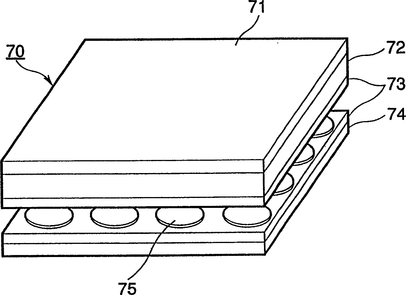
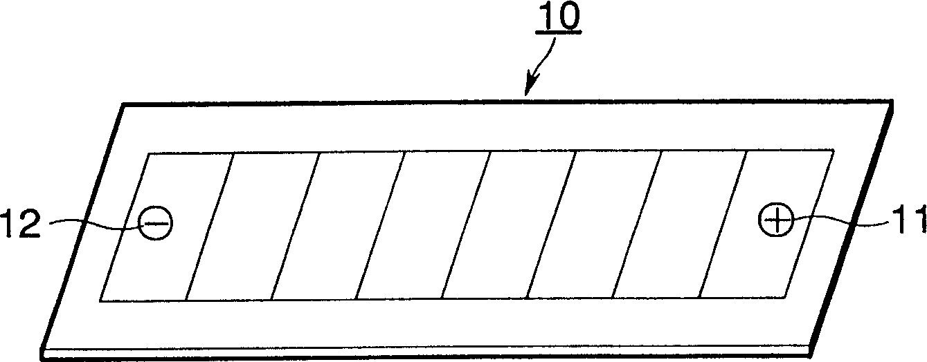
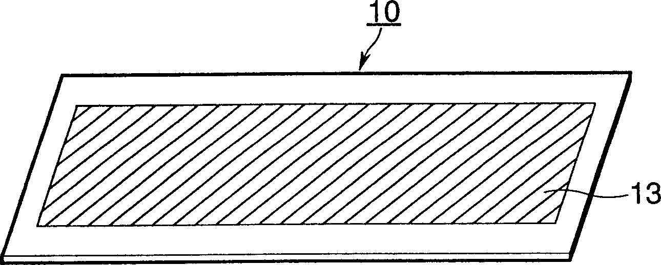
In order to prevent damage to a surface of a solar cell module during production and in order to increase productivity, a colored, light-stansmissive, adhesive film is stuck on the light-receiving surface side of the solar cell module.

Description

[0001] This application is a divisional application of the patent application for invention with application number 98114734.8 and titled "Method for Manufacturing Solar Cell Module". technical field [0002] The present invention relates to a solar cell module, a manufacturing method thereof, and a method for installing the solar cell module. In particular, the present invention relates to improvements in productivity and assembly rate of solar cell modules, and a method of manufacturing and an installation method of a solar cell module that hardly damage the surface of the solar cell module during the manufacture of the solar cell module or during the installation of the solar cell module . Background technique [0003] In recent years, there has been a global increase in awareness of environmental issues, one of which is the 2 There is a deeper understanding of the phenomenon of global warming, and the expectation for clean energy is becoming stronger and stronger. Rece...

Claims


Application Information

Patent Timeline
Patent Type & Authority Applications(China)
IPC IPC(8): H01L31/042H01L31/048
CPCH02S20/23Y02B10/12Y02E10/50H01L31/0482H01L31/048Y02B10/10
Inventor 高林明治
Owner CANON KK
Why Eureka
Eureka Blog
Learn More