
Automatic production line for punch

An automatic production line and punching technology, applied in the field of mechanical processing punching machines, can solve the problems of low continuous productivity and automation, high labor intensity, and increase production costs, so as to improve labor intensity and production environment, reduce operating labor, and improve The effect of production efficiency

Inactive Publication Date: 2004-08-25
天津职业大学
View PDF1 Cites 28 Cited by
  • Summary
  • Abstract
  • Description
  • Claims
  • Application Information

AI Technical Summary

Problems solved by technology

[0006] 1. High labor intensity and poor safety
[0007] There is basically no equipment for each process before and after the existing punching machine. It is mainly operated by hand, and the labor intensity is extremely high. Especially for large-scale punching equipment, the structure is huge, the punching pressure is high, and the material size is also large. It is very difficult and inconvenient for the operator to carry. It is also easy to be scratched, and there is a potential safety hazard
[0008] 2. Non-automated production, low productivity
[0009] The processes before and after the existing punching machine are all manually operated, which requires many people and low efficiency, especially the production time and auxiliary production time are difficult to control, the production rhythm is uneven and difficult to improve, and it is not suitable for mass production and modern management.
[0010] 3. Unstable production quality
[0011] Manual operation, the product quality will be affected by human factors, it is difficult to guarantee; if a certain quality control method is added, the production cost will be increased
[0012] 4. Manual operation is scattered, occupying a large area of ​​the site
But it is far from the requirements of the production line, and it cannot even be called a production line in the modern sense. The continuous production and automation of this equipment are still very low, and it is far from meeting the requirements of modern punch automatic production line equipment.

Method used


Image

  • Automatic production line for punch
  • Automatic production line for punch
  • Automatic production line for punch

Examples


Embodiment Construction

[0031] The present invention will be further described below in conjunction with the embodiments and drawings:

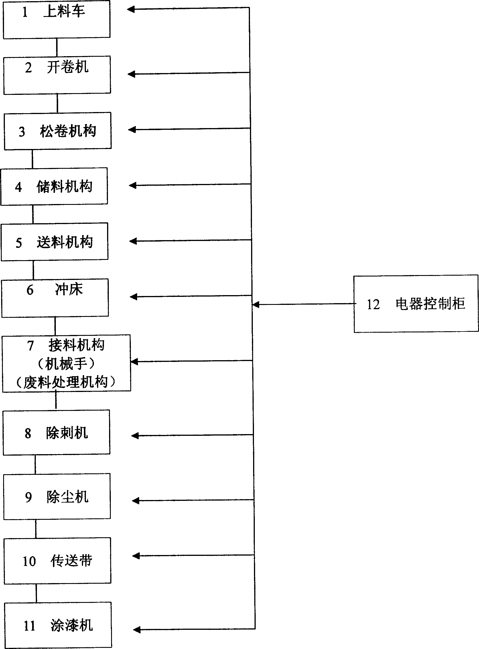
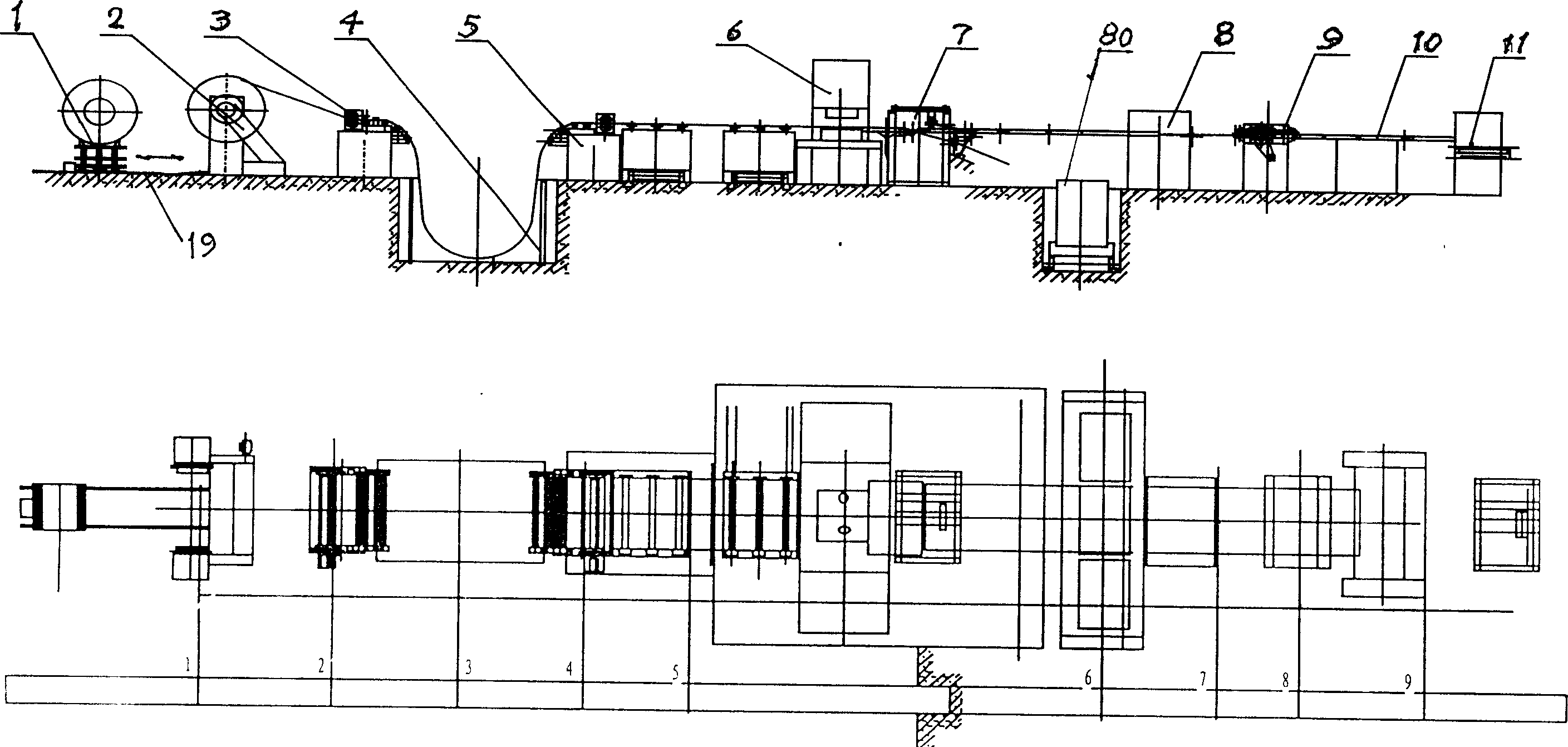
[0032] A punch automatic production line designed by the present invention (hereinafter referred to as the production line, see figure 1 , 2 ), including the deburring machine 8, the conveyor belt 10 and the painting machine 11 which are sequentially connected after the punch 6, characterized in that the uncoiler 2, the unwinding mechanism 3, the storage mechanism 4 and the feeding mechanism are sequentially connected before the punch 6 Mechanism 5; a material receiving mechanism 7 is also connected between the punch 6 and the puncture machine 8; a dust remover 9 is also connected between the puncture machine 8 and the conveyor belt 10; the connection mentioned here refers to the process Process connection, not mechanical connection. For example, between the uncoiler 2 and the unwinding mechanism 3, and between the unwinding mechanism 3 and the storage mechanism 4, onl...


PUM


Abstract

The present invention relates to an automatic production line of punching machine. It includes successively-connected burring machine, belt conveyer and paint-coating machine after the punching machine. It is characterized by that before punching machine the dewiling mechanism, coil-opening mechanism, material-storing mechanism and material-feeding mechanism are successively connected, between punching machine and burring machine a material-receiving mechanism is connected, and between the burring machine and belt conveyer a dust remover is connected. The described material-receiving mechanism mainly includes mechanical arm, rolling mechanism, cutting mechanism and waste material processing mechanism. All the mechanisms are controlled by electric control cabinet and correspondent program.

Description

Technical field [0001] The present invention relates to the technology of machining punch presses, in particular to the technology of continuous processing of metal sheets or coils using punch presses to manufacture products. The main international patent classification number is proposed to be Int.Cl 7 .B21D 28 / 00. Background technique [0002] Punch is a commonly used equipment in mechanical processing, mainly used for stamping metal sheets or coils to directly obtain products shaped according to the model. [0003] At present, the production process of punching machines, especially large-scale punching machines, is mostly manual feeding and manual discharging. The typical process is as follows: [0004] Manual cutting→manual feeding→punching→manual receiving→manual coding. [0005] Its production obviously has the following main problems: [0006] 1. High labor intensity and poor safety [0007] There are basically no equipment for each process before and after the existing pu...

Claims


Application Information

Patent Timeline
IPC IPC(8): B21D28/00
Inventor 付植桐张永飞李茹吕英芳李运生孙茂华王凯邢朝明
Owner 天津职业大学
Learn More