Terminal structure of direct electric current superconducting cable and dc superconducting cable line

A technology of superconducting cable and direct current, which is used in cable accessories, cable terminals, superconducting devices and other directions of low temperature cables

Inactive Publication Date: 2004-09-01
SUMITOMO ELECTRIC IND LTD
View PDF1 Cites 9 Cited by
  • Summary
  • Abstract
  • Description
  • Claims
  • Application Information

AI Technical Summary

Problems solved by technology

However, depending on the number of power supplies, multiple cables must be used, and space for wiring the cables is necessary

Method used


Image

  • Terminal structure of direct electric current superconducting cable and dc superconducting cable line
  • Terminal structure of direct electric current superconducting cable and dc superconducting cable line
  • Terminal structure of direct electric current superconducting cable and dc superconducting cable line

Examples


Embodiment Construction

[0017] Hereinafter, a detailed description of the present invention will be given.

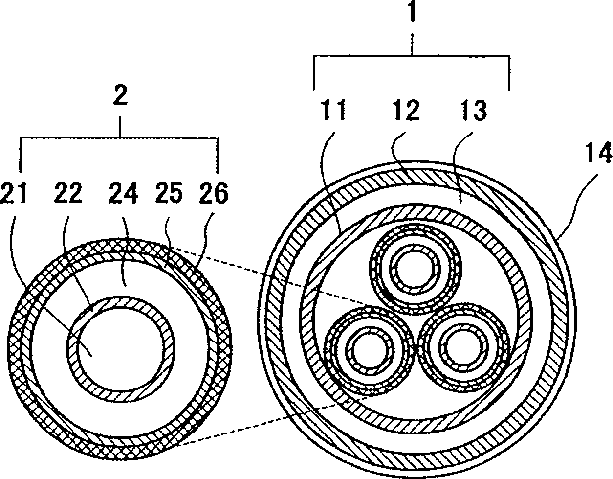
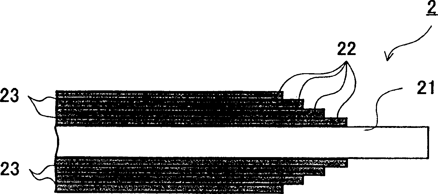
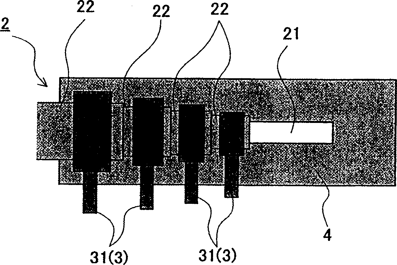
[0018] In the drawings, the same reference numerals are assigned to the same elements, and their explanations will not be repeated. The dimensional ratios in the drawings are not always the same as those described in the specification. figure 1 is a cross-sectional view of a superconducting cable according to the present invention, while figure 2 The termination structure of the conductor portion in the core of the superconducting cable is shown. image 3 and Figure 4 The terminal structure of the conductor elements of the superconducting cable core connected to the output conductor is schematically illustrated. Figure 5 is a schematic diagram showing the structure of a cable line using the superconducting cable, and an explanation about the structure of the cable core is given in the drawing.

[0019] 【Overall structure of superconducting cable】

[0020] Superconducting cables can hav...


PUM


Abstract

A terminal structure of a direct electric current superconducting cable of the present invention is such that the end portions of superconducting layers (22) provided over a core material (21) are exposed in a step-by-step manner from an outer layer to an inner layer, and outgoing conductors (32) made of a normal conductive material are individually connected with the exposed end portions of the respective superconducting layers. A direct electric current superconducting cable line has power supplies, loads, and a superconducting cable for supplying electric power from the power supplies to the loads, and at least one end of the superconducting cable has the above-mentioned terminal structure and the outgoing conductors are connected individually with the power supplies or the loads. <??>By employing the above-mentioned terminal structure of the direct electric current superconducting cable and the direct electric current superconducting cable line, the power transmission of multiple circuits is made possible with a single superconducting cable such that increase of the electric current, decrease of the needed space and decrease of the transmission loss can be achieved.

Description

technical field [0001] The invention relates to a terminal structure of a direct current (DC) superconducting cable and a line of the DC superconducting cable. Background technique [0002] The superconductor of a superconducting cable generally consists of a superconducting layer formed by helically winding a superconducting wire around a core material (hereinafter referred to as "former"). When a superconducting cable is used as a DC cable, welding is performed to join the superconductors together or to connect the ends of the superconductors to wires made of conventional conductors (for example, refer to Japanese Patent Application No. 10-228933). Some superconducting cables have a superconductor having a multilayer structure consisting of a plurality of superconducting layers (for example, see Japanese Patent Application No. 10-228933 image 3 ). In this case, as appended to the 10-228933 patent publication image 3 As shown, welding is performed simultaneously so that ...

Claims


Application Information

Patent Timeline
Patent Type & Authority Applications(China)
IPC IPC(8): H01B13/00H01B12/02H01R4/68H01R24/58H02G1/14H02G15/04
CPCY02E40/648H01R4/68H02G15/34Y02E40/60H01B12/02
Inventor 广瀬正幸
Owner SUMITOMO ELECTRIC IND LTD
Why Eureka
Try Eureka