Sync control device

A technology of synchronous control and control device, applied in the direction of automatic control device, grinding automatic control device, feeding device, etc., can solve the problems of motor pulling, lowering, motor or amplifier heating processing accuracy, etc., and achieve the effect of reducing stress

Inactive Publication Date: 2004-09-08
FANUC LTD
View PDF1 Cites 48 Cited by
  • Summary
  • Abstract
  • Description
  • Claims
  • Application Information

AI Technical Summary

Problems solved by technology

[0005] In this case, if the rigidity between the motors is high, the phenomenon that the motors pull each other will occur, and stress will be generated between the motors, causing problems such as heating of the motor or the amplifier, or a decrease in processing accuracy.

Method used


Image

  • Sync control device
  • Sync control device
  • Sync control device

Examples


Embodiment Construction

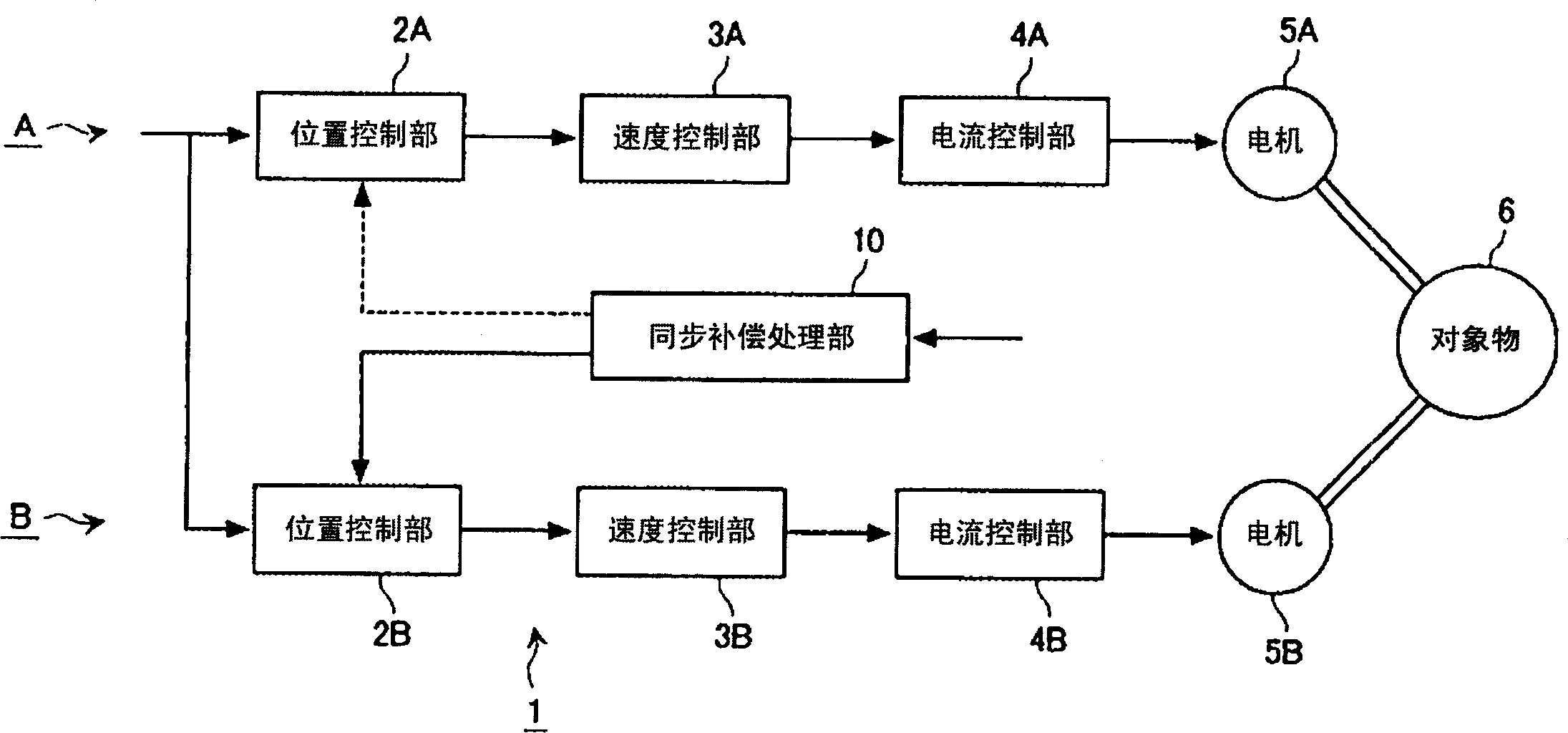
[0051] The control of multiple servo motors consists of a host control device such as a numerical controller or a host control unit, a shared RAM, a digital servo circuit, a power amplifier, and multiple motors. These motors are connected to the object (workpiece) to form a drive system. .

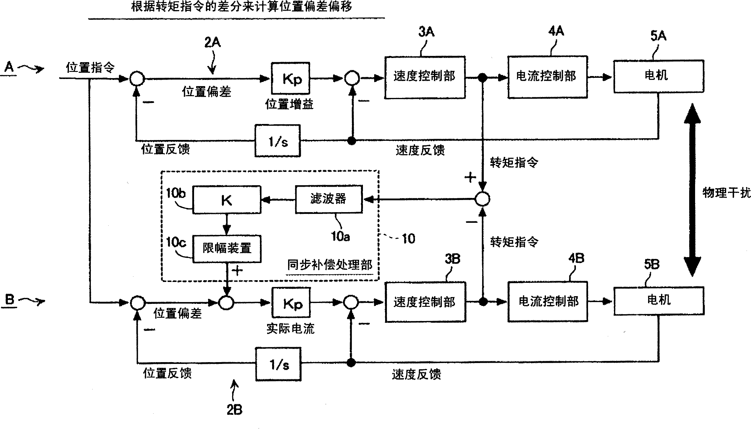
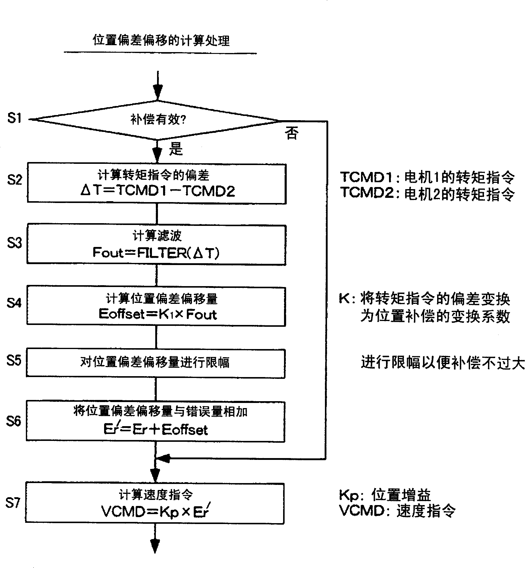
[0052] The processor of the digital servo circuit reads the position command from the upper control device or the upper control unit through the shared RAM, and performs position closed-loop processing, speed closed-loop processing and current closed-loop processing. Subtract the feedback value from the position command to obtain the position deviation, multiply the position deviation by the position gain, perform position closed-loop control, obtain the speed command, subtract the speed feedback value from the speed command, obtain the speed deviation, and perform Proportional, integral control and other speed closed-loop processing to obtain torque command (current command). Further, th...


PUM


Abstract

There is provided a synchronous control device (1) for driving the same control object (6) with two servomotors (5A,5B). The synchronous control device detects the physical quantity that represents the difference between the forces on the two servomotors (5A,5B), and, on the basis of the detected value, reduces the force that acts between the two servomotors (5A,5B).

Description

technical field [0001] The present invention relates to a drive control device for a servo motor used as a drive source of a working machine, an industrial machine, a robot, etc. controlled by a numerical controller (NC device). Background technique [0002] In machine tools, synchronous control is sometimes performed to drive a single object with a plurality of motors. For example, when a large workpiece such as the C-axis of the crank grinding disc is driven by 1 servo motor, bending may occur in the workpiece due to machining disturbance. Such bending of the workpiece affects machining accuracy. For the bending of the workpiece, two servo motors are arranged on the workpiece, and in order to ensure that the two servo motors are synchronously controlled, the bending of the workpiece is reduced. [0003] In this synchronous control, servo motors are installed on two axes connected to the workpiece, and each servo motor is controlled by its own servo circuit. Each servo c...

Claims


Application Information

Patent Timeline
Patent Type & Authority Applications(China)
IPC IPC(8): B23Q15/00B24B51/00G05B19/18G05B19/19G05D3/00G05D3/12H02P5/00H02P5/52H02P5/54
CPCH02P5/52G05B2219/34027
Inventor 岩下平辅河村宏之汤志炜
Owner FANUC LTD
Why Eureka
Try Eureka