
Kilomega Ethernet passive optical network up-flow-section integrating bandwidth distributing method

A bandwidth allocation method and passive optical network technology, which are used in data exchange networks, selection devices for multiplexing systems, electromagnetic wave transmission systems, etc., which can solve the problem of complex hardware implementation, time-consuming to rewrite table entries one by one, and bandwidth update speed limitations. And other issues

Inactive Publication Date: 2004-09-15
FENGHUO COMM SCI & TECH CO LTD
View PDF0 Cites 3 Cited by
  • Summary
  • Abstract
  • Description
  • Claims
  • Application Information

AI Technical Summary

Problems solved by technology

This allocation method is relatively simple, but has the following disadvantages: 1. The accuracy is poor, and the bandwidth granularity is only 1 / 4800 of the total bandwidth. For the total bandwidth of 155M, the minimum value of the bandwidth change is 155M / 4800=32k; 2. Hardware The implementation is complicated, using 2×4800 registers, and 2×4800 bytes are used in the hardware master and backup registers; 3. The bandwidth update speed is low. Since there are 4800 table entries, it is time-consuming to modify the bandwidth and rewrite the table entries one by one, and the bandwidth The update speed is limited; 4. The corresponding asynchronous transfer mode cell has a fixed packet length, which is not suitable for the Ethernet packet, and the Ethernet packet itself is variable in length
Due to the above-mentioned shortcomings, the bandwidth group control table allocation method of the asynchronous transfer mode passive optical network is not suitable for application in the bandwidth allocation of the upstream flow of the Gigabit Ethernet passive optical network

Method used


Image

  • Kilomega Ethernet passive optical network up-flow-section integrating bandwidth distributing method
  • Kilomega Ethernet passive optical network up-flow-section integrating bandwidth distributing method
  • Kilomega Ethernet passive optical network up-flow-section integrating bandwidth distributing method

Examples


Embodiment Construction

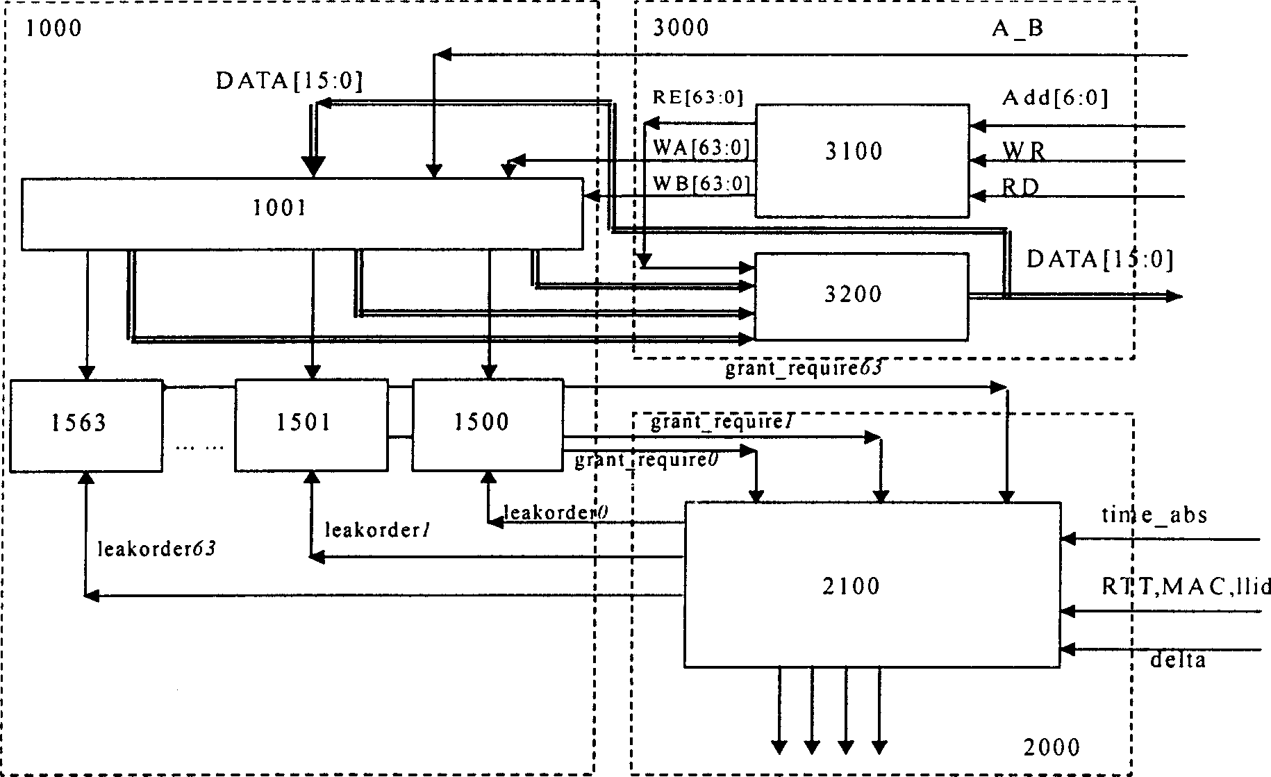
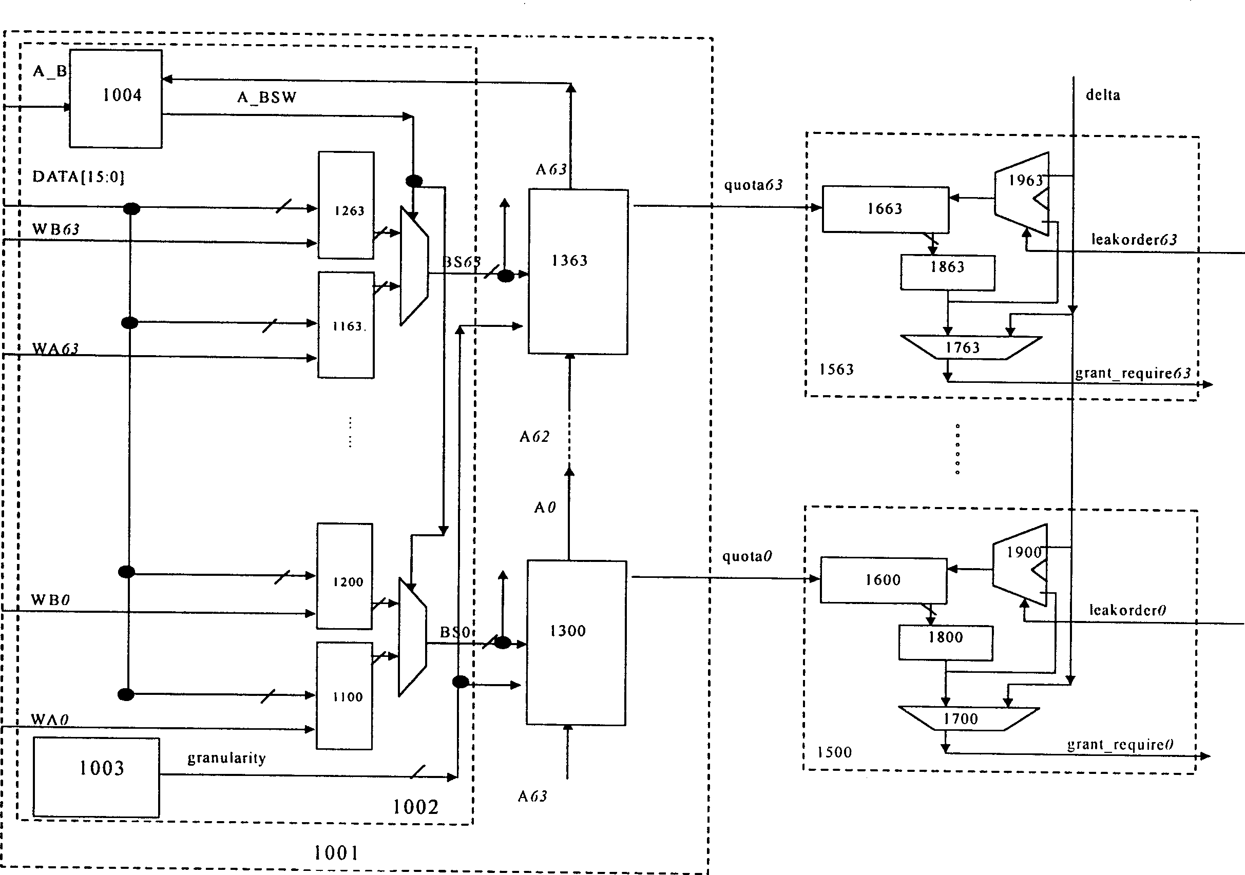
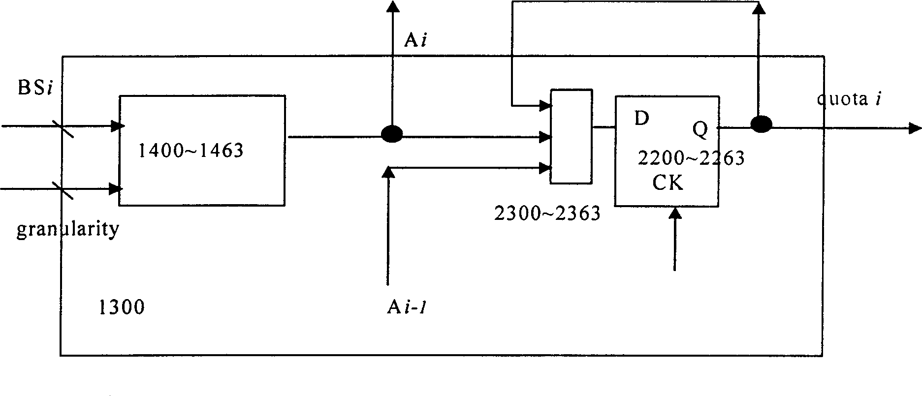
[0043] figure 1It is a logical block diagram of segmental integral bandwidth allocation hardware. The hardware part of the present invention includes an integral bandwidth designator 1000 , a grant generation circuit 2000 and a microprocessor interface 3000 . The integral bandwidth designator 1000 is logically connected with the microprocessor interface 3000 and the authorization generation circuit 2000, can complete the bandwidth designation, assign the time slot position to the corresponding remote optical network unit ONU, and specify the generated time slot position code An authorization message is generated, which will be sent to the remote optical network unit ONU. The integral bandwidth designator 1000 completes the bandwidth designation through the microprocessor interface 3000, and its specific process is: the microprocessor interface 3000 includes two circuit modules, one is a read-write control circuit 3100, and the other is a tri-state gate group circuit 3200. Th...


PUM


Abstract

Based on sectional type list of tail coordinates about quantity of subchannel bandwidth occupied as prepared distribution scheme, assigned quantities of subchannel bandwidth are realized. Using integral processing unit collects quantities of subchannel bandwidth. Sending out signal of requesting bandwidth according to size authorized by EPON system completes granting for quantity information so as to realize bandwidth distribution of up going flow on EPON system. Steps for bandwidth distribution are as following: interface of microprocessor sends out enable signal for reading / writing control; based on prepared distribution scheme, bandwidth designator converts and designates subchannel bandwidth to realize rearrangement of main / standby multiplexing; integral bucket corrects quantities of subchannel bandwidth occupied; based on request, authorization generating circuit sends signal of leaking command to control leaking operation of integral bucket so as to realize distribution.

Description

technical field [0001] The invention relates to an upstream bandwidth allocation method based on a Gigabit Ethernet passive optical network (Ethernet Passive Optical Network, referred to as EPON) system, which belongs to the field of optical fiber communication, and in particular relates to a segmented integration method based on an EPON upstream High precision bandwidth allocation method. technical background [0002] In the prior art, the most similar to the present invention is the bandwidth group control table allocation method based on the asynchronous transfer mode passive optical network, and a kind of Sbus SAR cell dismantling device adopting this type of allocation method is TNETA1560 of TI Company. The bandwidth group control table allocation method based on the asynchronous transfer mode passive optical network is a fixed bandwidth method, that is, a 1200 double word (4800 entries in total, ie 4800 bytes) bandwidth group control table is ...

Claims


Application Information

Patent Timeline
IPC IPC(8): H04L47/21H04L47/525H04Q3/52H04Q11/00
Inventor 何岩陈丽沈羽纶朱丽丽杨柳
Owner FENGHUO COMM SCI & TECH CO LTD
Learn More