Optical head, optical information recording/reproducing device and applied apparatus

An optical information and reproduction device technology, applied in the field of optical heads, can solve the problems of aberration deterioration, beam shaping magnification change, impracticality, etc., and achieve the effect of improving light utilization rate

Active Publication Date: 2004-09-22
PANASONIC CORP
View PDF0 Cites 12 Cited by
  • Summary
  • Abstract
  • Description
  • Claims
  • Application Information

AI Technical Summary

Problems solved by technology

When the beam shaping magnification is set to a factor of at least 2 in order to obtain a substantially circular beam, since the cylindrical surface of the sphere exhibits a higher-order aberration of at least 0.06λ (where λ is the wavelength), thus make it impractical
[0011] Additionally, using Figure 17 Cylindrical lens 302a and cylindrical lens 302b in the second conventional example shown, and with this beam shaping magnification set to a factor of 2 or more, the same higher-order aberrations occur
In addition, the cylindrical lens 302a and the cylindrical lens 302b are spatially separated, so their spacing may change due to temperature changes, and the magnification of the beam shaping may also change, resulting in the problem of aberration deterioration.

Method used


Image

  • Optical head, optical information recording/reproducing device and applied apparatus
  • Optical head, optical information recording/reproducing device and applied apparatus
  • Optical head, optical information recording/reproducing device and applied apparatus

Examples


Embodiment 1

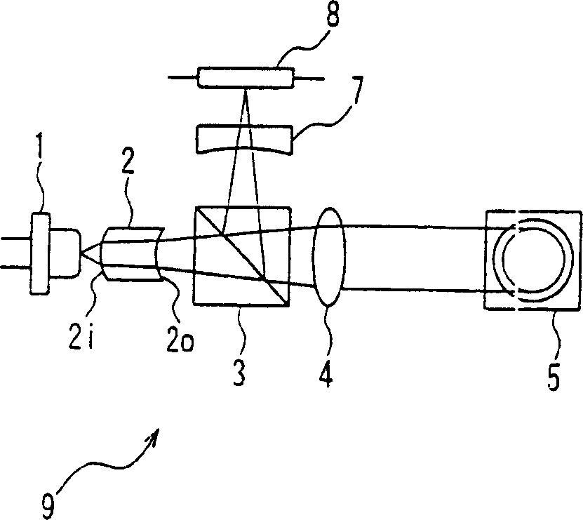
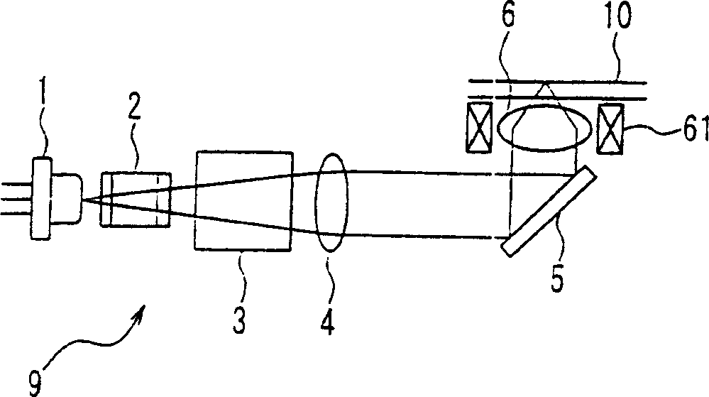
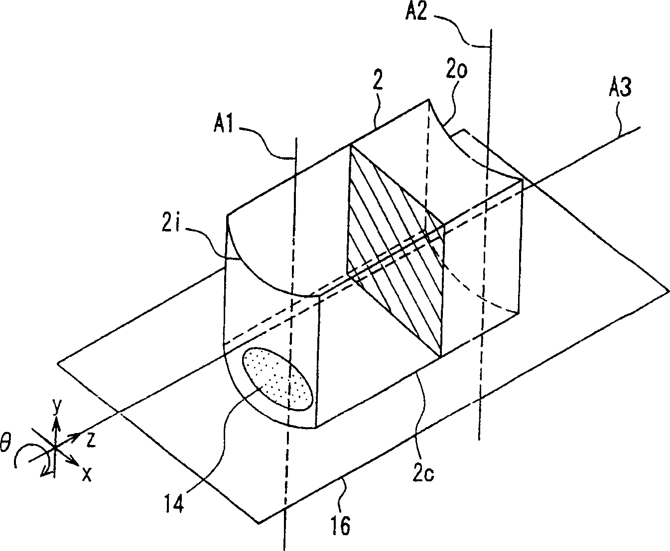
[0065] Figure 1A and 1B An optical head 9 according to Embodiment 1 of the present invention is shown. Figure 1A is the top view of the optical head 9, and Figure 1B is a side view of the optical head 9. The beam emitted from the light source 1 is emitted from one end face of the thin active layer so that the shape of the beam is elliptical, and the ratio between the minor axis and the major axis of the beam is about 1:3. Through the following beam shaping lens 2, the elliptical diverging beam emitted from the light source 1 is shaped into a substantially circular diverging beam, the beam passes through the beam splitting prism 3, and is collimated into a substantially parallel beam through the collimating lens 4, It is reflected by the mirror 5, converged by the objective lens 6, and then irradiated on the optical disc 10. The light beam reflected by the optical disc 10 returns along the opposite path, is reflected by the dichroic prism 3 , passes through the detection...

Embodiment 2

[0087] Figure 4A and 4B An optical head 29 according to Embodiment 2 of the present invention is shown. Different from Embodiment 1, the beam shaping lens 22 is composed of a cylindrical lens 22a and a cylindrical lens 22b. Other structural aspects are the same as those in Embodiment 1, so details will not be repeated for these parts. Figure 5 is a perspective view of the beam shaping lens 22.

[0088] Typically, axial rotational symmetry is used in lens manufacture so that rotational adjustments of the front and back of the lens are not required. However, in a lens without axial rotational symmetry, such as the beam shaping lens 2 of Embodiment 1, it is necessary to pay attention to the rotational error of the two surfaces. When the magnification of the beam shaping is about a factor of 2, the aberration due to the rotation error will become large. Therefore, the tolerable rotation error is limited to less than 0.05 degrees. In Embodiment 2, the beam shaping lens 22 i...

Embodiment 3

[0100] Figure 7A and 7B Embodiment 3 according to the present invention is shown, and shows the light source 1, the beam shaping lens 22 and its peripheral parts. Other aspects are the same as in Embodiment 1, so these parts will not be repeated. The details of the beam shaping lens 22 are the same as those described in Embodiment 1 or Embodiment 1.

[0101] Usually, due to the manufacturing error of the light source 1, the light-emitting point 21 will deviate by about 0.1 mm, and the optical axis will be inclined by about 3°. In order to correct this deviation, positioning adjustment and tilt adjustment of the light source 1 must be performed. Such as Figure 7A As shown, the light source 1 is fixed on the bracket 11 by press fit or caulking. The bracket 11 can be tilted and adjusted relative to the adjustment plate 12 , so as to correct the tilt of the optical axis of the light source 1 . The adjustment plate 12 can be positioned and adjusted relative to the optical b...


PUM


Abstract

An optical head is provided that increases the light utilization efficiency and that can be adapted to high-speed recording and double-layer disks. A beam-shaping lens (2) that shapes an elliptical beam emitted from a light source (1) into a substantially circular beam has a pair of cylindrical surfaces (2i, 2o) that are curved in the same direction. The cylindrical surface (2i) that is closer to the light source (1) is an aspherical surface, and the cylindrical surface (2o) that is further away from the light source (1) is a spherical surface. Thus, an optical head is obtained, with which aberrations can be kept low, even when the beam-shaping magnifying power is about a factor 2.

Description

technical field [0001] The present invention relates to an optical head, an optical information recording / reproducing device that records or reproduces information by irradiating light from the optical head onto an optical disc, and a computer using the optical head and the optical information recording / reproducing device, a video recording / reproducing device, Video reproduction devices, servers and car navigation systems. Background technique [0002] An optical disc called a DVD (Digital Versatile Disc) is commercially available as a high-density, high-capacity optical information recording medium. Such optical discs have been rapidly popularized in recent years as recording media capable of recording images, music, and computer data. In recent years, progress has been made in developing next-generation optical discs with even higher recording densities. Next-generation optical disks are expected to replace video tapes of VTRs (Video Tape Recorders) commonly used at pres...

Claims


Application Information

Patent Timeline
Patent Type & Authority Applications(China)
IPC IPC(8): G01C21/00G11B7/08G11B7/095G11B7/135G11B7/22
CPCG11B7/1356G11B7/1376G11B7/1374G11B7/0956G11B7/1378G11B7/1398G11B7/082G11B7/1362G01C21/00G11B7/22G11B7/13922G11B7/08
Inventor 安田昭博金马庆明田中康弘清水义之
Owner PANASONIC CORP
Why Eureka
Try Eureka