Photodynamic therapy lamp

A technology of photodynamic therapy and light-emitting diodes, applied in the field of lighting sources, can solve problems such as high cost, long treatment time, limited light output, and complexity

Inactive Publication Date: 2004-09-22
弗托库尔公司 +1
View PDF39 Cites 7 Cited by
  • Summary
  • Abstract
  • Description
  • Claims
  • Application Information

AI Technical Summary

Problems solved by technology

Other disadvantages of using known PTD-LED technology include higher cost and complexity due to liquid crystal ...

Method used


Image

  • Photodynamic therapy lamp
  • Photodynamic therapy lamp
  • Photodynamic therapy lamp

Examples


no. 1 example

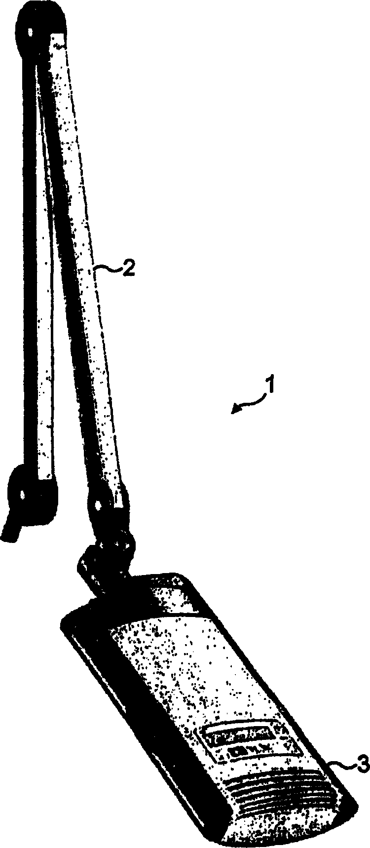
[0046] see first figure 1 , a phototherapy lamp includes a support balance arm 2 with a clamp (not shown), an external power supply (not shown), and a lamp base 3. This figure shows the first embodiment of the invention, while the second embodiment is also provided with a similar arm (see Figure 7 ). The arm enables the light to be fixed to a table-like surface in, for example, a doctor's office. The arm is substantially conventional and allows the lamp head to be movable into position over a part of the body of the patient to be treated.

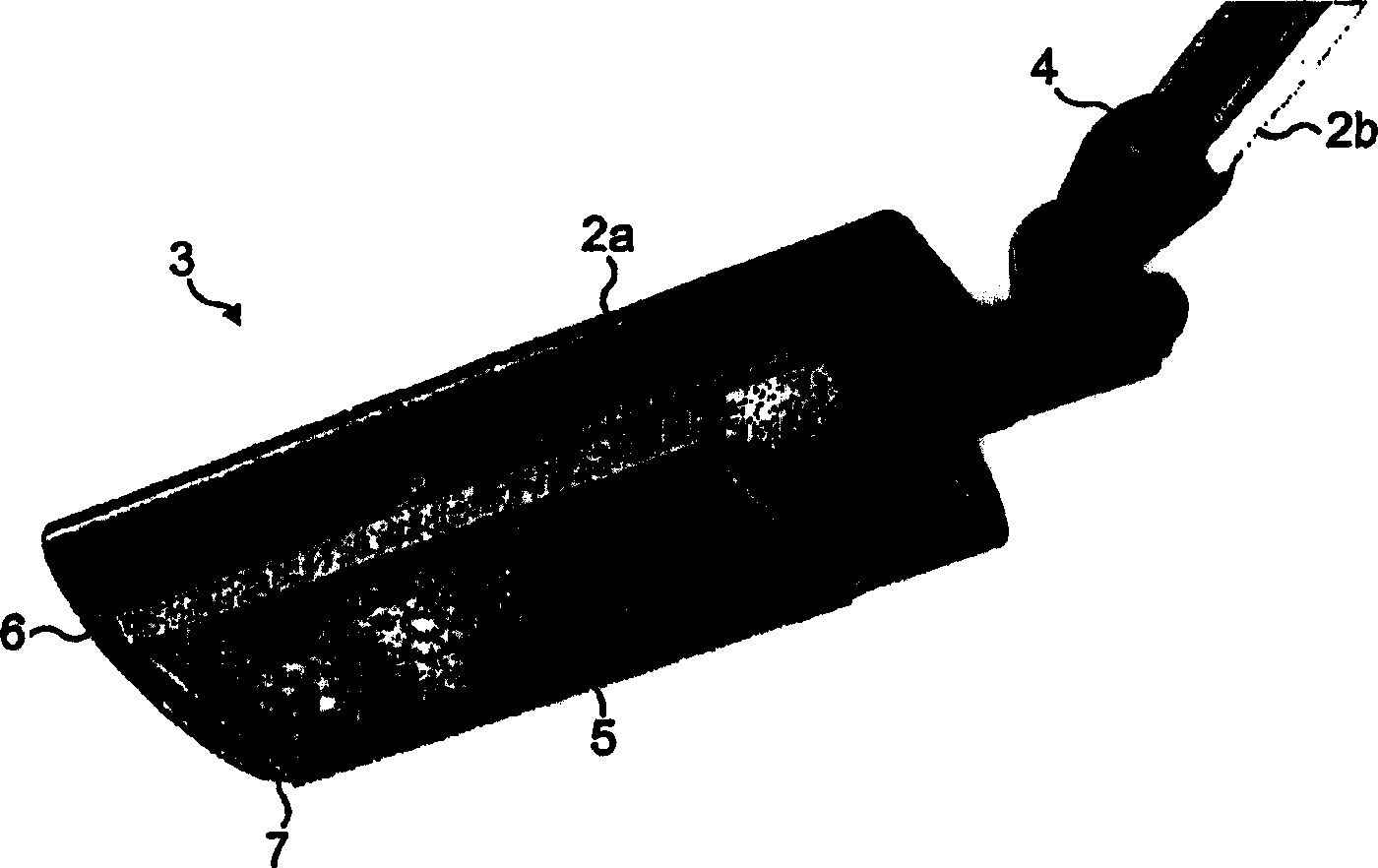
[0047] now turn to look figure 2 , it can be seen that the lamp cap 3 of the first embodiment is pivotally mounted to a side arm 2a whose shape generally conforms to the external shape of the lamp cap. (this is in Figure 5 Perhaps it can be seen more clearly in Figure 5 It can be seen that the side arm 2a is engaged with the pivot pin 2c. ) The side arm itself is connected to the main arm 2b via a swivel joint 4. The swivel join...


PUM


Abstract

A photodynamic therapy lamp has a cover (10, 11, 12, 13) which contains a light source formed from two arrays (20) of LEDs (21). The LEDs are arranged in a honeycomb pattern and have a peak wavelength of 630-640 nm. Beneath the LEDs is a lens pack (22) containing a lens (23) for each LED. Beneath this is a diffuser (7). The lenses are arranged in a honeycomb pattern and serve to concentrate the light in a substantially parallel and narrow beam.

Description

technical field [0001] The present invention relates to an illumination source (also called lamp) for photodynamic therapy (PDT) Background technique [0002] Photodynamic therapy (PDT) is a developing therapy currently used to treat various tumors as well as non-malignant diseases including infection, wound healing and various skin diseases. The method is based on the interaction of a specialized oxygen photosensitizer and light. Clinical experience has shown the superiority of PDT over other therapies for the treatment of several pathological conditions including acne keratosis and various skin cancers. General background information on the clinical application of PDT can be found in US6225333, US6136841, US6114321, US6107466, US6036941, US5965598 and US5952329. [0003] Several photosensitizers are commercially available and in preclinical or clinical development, including 5-aminolevulinic acid (5-ALA), 5-ALA derivatives and porphyrin derivatives. Other photosensitize...

Claims


Application Information

Patent Timeline
IPC IPC(8): A61B19/00A61N5/00A61N5/06
CPCA61N2005/0652A61N2005/0642A61B2019/4036A61N5/062A61N2005/007A61B2019/409A61N2005/005A61B2090/0436A61B2090/049A61N5/06
Inventor 莫滕·格罗塞思贾尔·斯凯德斯沃尔托罗尔夫·C·韦德伯格乔恩·E·布雷恩登
Owner 弗托库尔公司
Why Eureka
Try Eureka