Display assembly

A technology for displays and liquid crystal displays, applied in static indicators, instruments, nonlinear optics, etc., can solve the problems of anisotropic conductive films not easy to stick, glass substrates cracked, machine glue residues, etc.

Active Publication Date: 2004-11-03
AU OPTRONICS CORP
View PDF0 Cites 5 Cited by
  • Summary
  • Abstract
  • Description
  • Claims
  • Application Information

AI Technical Summary

Problems solved by technology

However, the area between two adjacent driver ICs 12 is, for example, a space 15 between the driver ICs 12a and 12b, or an area between two adjacent pin groups 13, such as It is at the interval 14 between the pin groups 13a and 13b. The adhesion of the anisotropic conductive film is poor, so the anisotropic conductive film is not easy to attach, which in turn affects the config

Method used


Image

  • Display assembly
  • Display assembly
  • Display assembly

Examples


no. 1 example

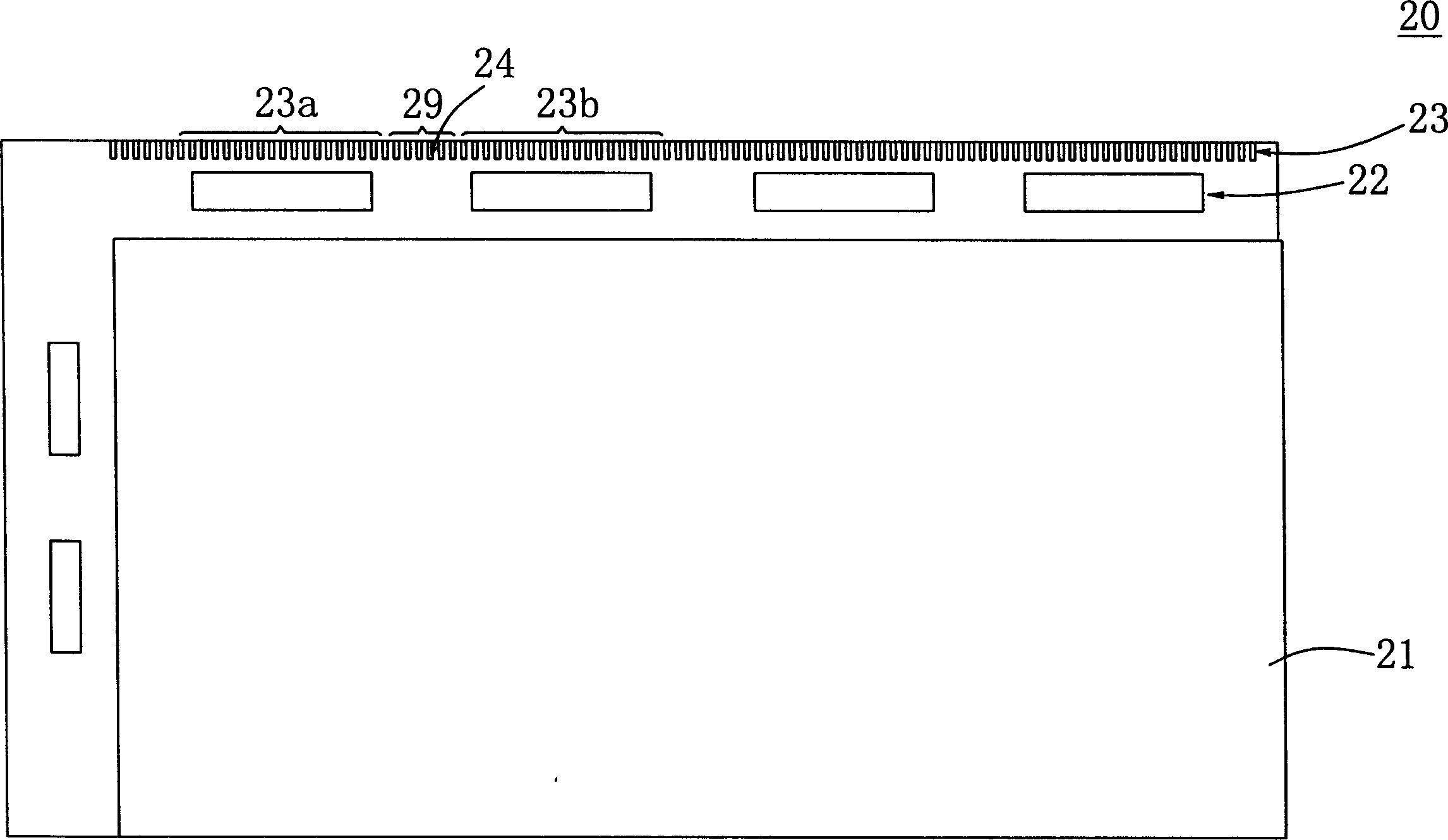
[0025] Please refer to figure 2 , which is a schematic diagram of the display assembly according to the first embodiment of the present invention. A plurality of driver ICs 22 are provided on the glass substrate 21 of the TFT substrate of the display module 20 . The driver ICs 22 are respectively disposed on the glass substrate 21 using chip-on-glass (COG) technology. A flexible printed circuit board (FPC) pin group 23 is correspondingly arranged on the outside of each driver IC 22 , and each FPC pin group 23 is composed of a plurality of FPC pins. A flexible printed circuit (not shown in the figure) is disposed on a plurality of FPC pin groups 23 by using an anisotropic conductive film.

[0026] A plurality of dummy leads 29 are arranged in the area between two adjacent FPC pin groups 23 , for example, at the space 24 between the FPC pin groups 23 a and 23 b. When the anisotropic conductive film is attached to the FPC pin groups 23a and 23b, the anisotropic conductive fil...

no. 2 example

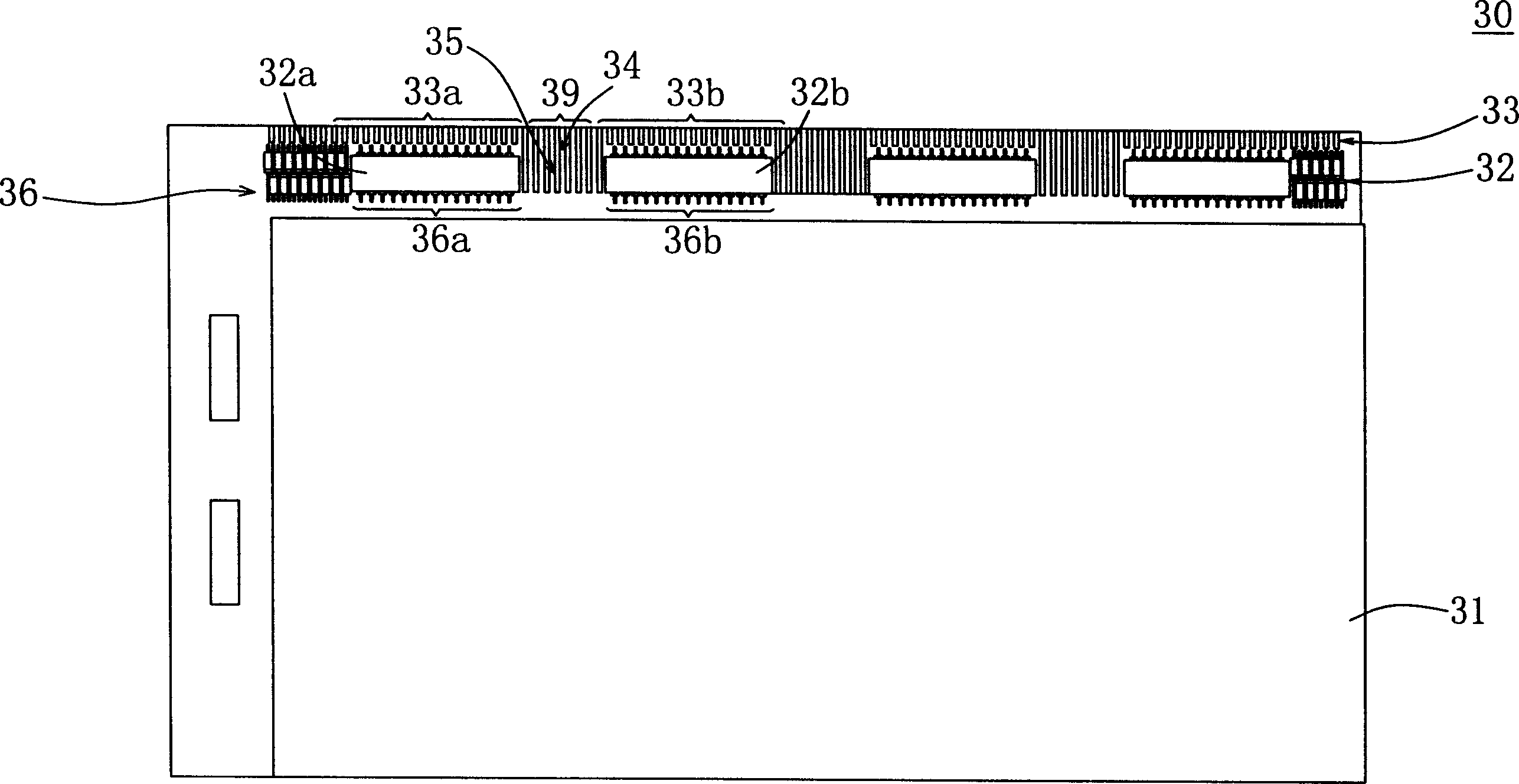
[0028] Please refer to image 3 , which is a schematic diagram of a display assembly according to a second embodiment of the present invention. A plurality of driver ICs 32 are provided on the glass substrate 31 of the TFT substrate of the display module 30 . The driver ICs 32 are respectively disposed on the glass substrate 31 using chip-on-glass (COG) technology.

[0029] There are a plurality of COG pin groups 36 on the glass substrate 31 , and each COG pin group 36 is composed of a plurality of COG pins respectively. The driving IC 32 is respectively disposed on the COG pin groups 36 by using an anisotropic conductive film, for example, the driving IC 32 a and the driving IC 32 b are respectively disposed on the COG pin groups 36 a and 36 b by using an anisotropic conductive film.

[0030] An FPC pin group 33 is correspondingly arranged on the outside of each driving IC 32 , and each FPC pin group 33 is composed of a plurality of FPC pins. A flexible printed circuit (no...

no. 3 example

[0034] Please refer to Figure 4 , which is a schematic diagram of a display assembly according to a third embodiment of the present invention. The glass substrate 41 of the TFT substrate of the display unit 40 has a plurality of driving ICs, such as driving ICs 42 a and 42 b . The driver ICs 42a and 42b are respectively disposed on the glass substrate 41 using chip-on-glass (COG) technology.

[0035] There are multiple COG pin groups on the glass substrate 41 , such as COG pin groups 46 a and 46 b , and each COG pin group is composed of multiple COG pins. The driving IC 42a and the driving IC 42b are disposed on the COG pin groups 46a and 46b respectively by using an anisotropic conductive film.

[0036] The outside of each driver IC is also correspondingly configured with an FPC pin group, for example, the outside of the driver IC42a and the driver IC42b are correspondingly equipped with FPC pin groups 43a and 43b, and each FPC pin group is composed of a plurality of FPC l...


PUM


Abstract

The display assembly includes one glass substrate, one first set of pins, one second set of pins and several dummy pins. The first set of pins and the second set of pins are configured in the edges of the glass substrate. One flexible printed circuit is configured on the first set of pins and the second set of pins via the first anisotropic conductive film. The dummy pins are set between the first set of pins and the second set of pins on the glass substrate. When the first anisotropic conductive film is adhered on the set of pins and the second set of pins, it is also adhered onto the dummy pins to increase the adhesion between the glass substrate and the first anisotropic conductive film. The design with increased wires of the present invention can raise the adhesion of the anisotropic conductive film, and this avoid forming residual adhesive and poor stitching.

Description

(1) Technical field [0001] The present invention relates to a display component, and in particular to a display component with increased adhesion of an anisotropic conductive film. (2) Background technology [0002] Due to the liquid crystal display has the advantages of full flat and thin body, small space occupation, thin panel thickness, light weight, flat right-angle display, low power consumption, low electromagnetic wave radiation, low heat radiation, etc., it gradually replaces the traditional Cathode Ray Tube monitors (Cathode Ray Tube, CRT) became the standard equipment of the computer. [0003] The manufacturing process of the liquid crystal display module (Liquid Crystal Display Module, LCD Module) is to use two glass substrates, respectively constructing a color filter and a thin-film transistor (Thin-film Transistor, TFT) on the surface of the two glass substrates, respectively. A color filter (Color Filter, CF) substrate is formed and a TFT substrate is formed...

Claims


Application Information

Patent Timeline
IPC IPC(8): G02F1/133G02F1/1345G02F1/136
Inventor 陈慧昌
Owner AU OPTRONICS CORP
Why Eureka
Try Eureka