
Device and method for inspecting an ionizing beam

一种检测装置、离子束的技术,应用在离子束检测装置和方法领域,能够解决困难、制造成本高等问题,达到降低制造成本的效果

Inactive Publication Date: 2004-11-03
CENT NAT DE LA RECH SCI (C N R S)
View PDF4 Cites 4 Cited by
  • Summary
  • Abstract
  • Description
  • Claims
  • Application Information

AI Technical Summary

Problems solved by technology

[0013] Such devices are very expensive to manufacture, especially in terms of fiber optic placement
Furthermore, the resolution of the device is limited by the size of the individual scintillation fibers and the number of scintillation fibers; in this case, by the number and diameter of the scintillation fibers
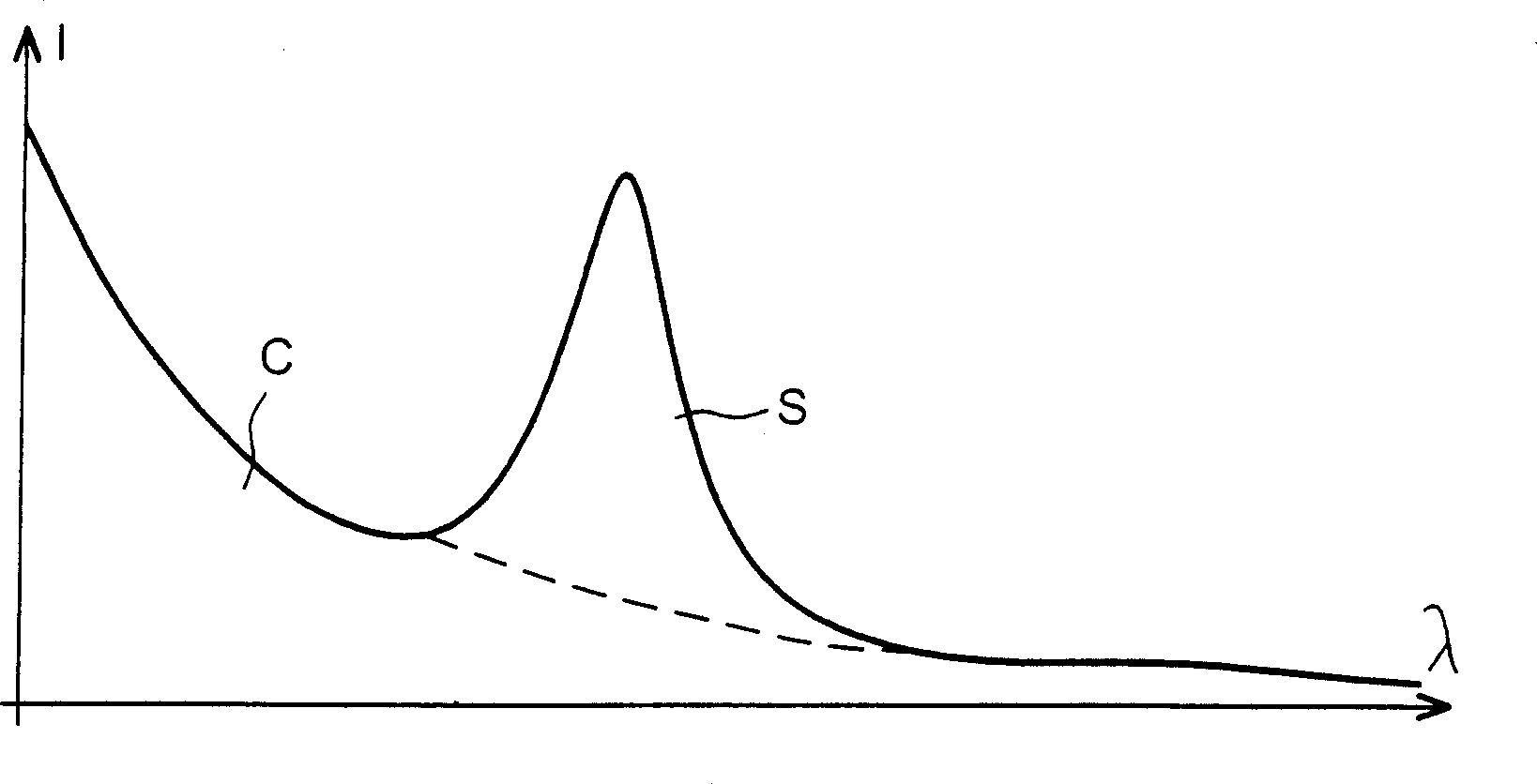
[0014] Finally, in addition to the scintillation phenomenon, there is also a stray light called Cherenkov light, which can cause difficulties

Method used


Image

  • Device and method for inspecting an ionizing beam
  • Device and method for inspecting an ionizing beam
  • Device and method for inspecting an ionizing beam

Examples


Embodiment Construction

[0084] In the following description, in order to facilitate the understanding of the interrelationships between different figures, the same, similar or equivalent components in each figure are denoted by the same reference numerals. In addition, in order to make the structures in the drawings clearer, not all elements are shown in the same scale.

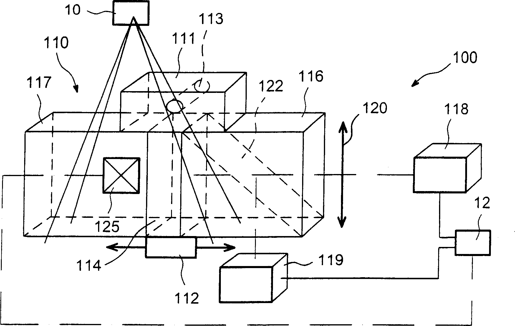
[0085] figure 1 shows a radiotherapy device with an ion beam emitting source 10, a device for detecting the ion beam 100 and a calculation unit 12 for establishing an ion beam distribution pattern. The distribution pattern is used to determine the expected radiation dose at any point in the patient's body irradiated by the ion beam.

[0086] The patient is modeled by a test head 110 on the test device. The detection head is mounted on an actuator 112 which moves it so that the detection head can move across the entire cross-sectional area of ​​the ion beam. The actuator may be designed for lateral movement in one or more directio...


PUM


Abstract

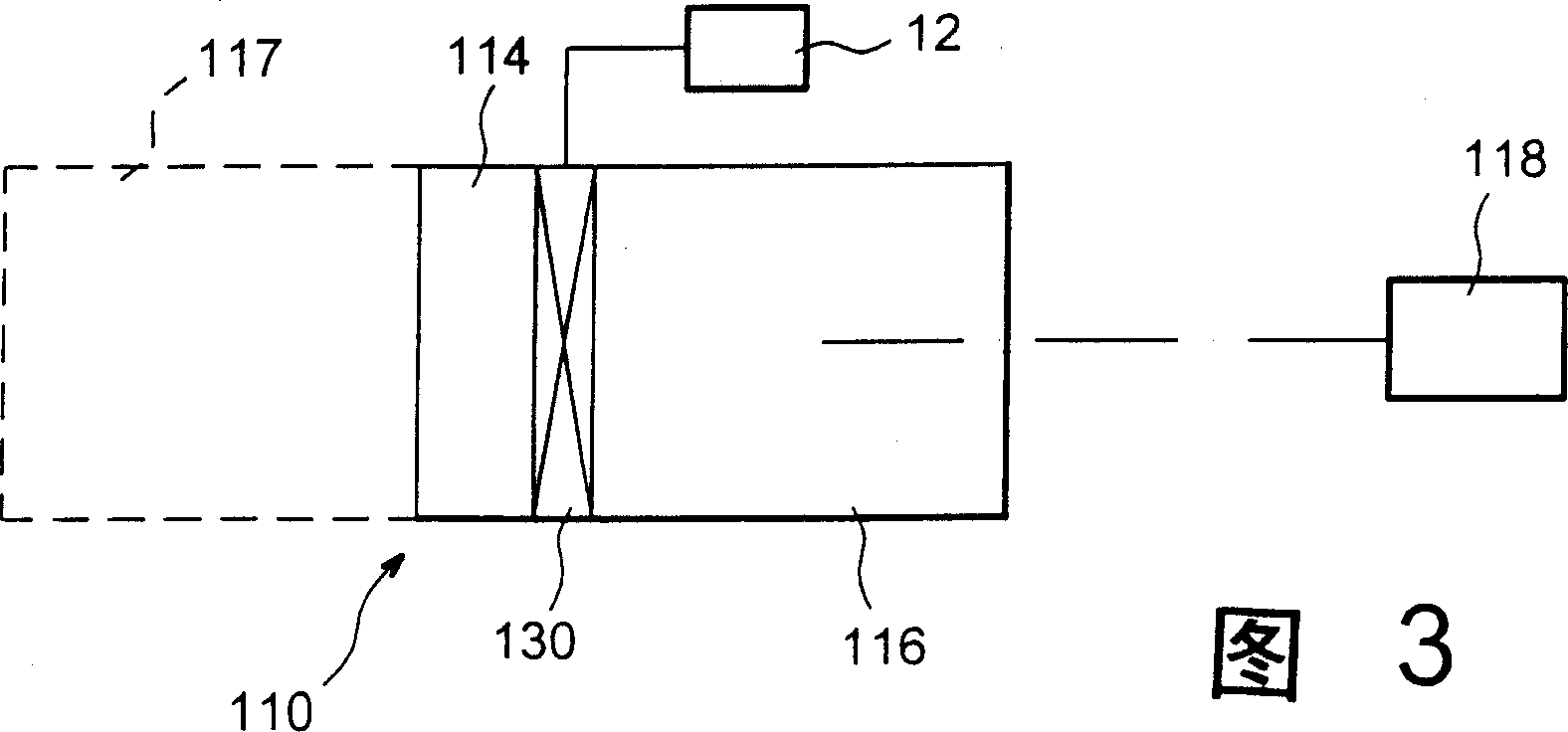
The invention relates to a beam inspection device, consisting of: an inspection head (110) comprising a scintillator (114) and at least one diffuser unit (116, 117) which is associated with said scintillator, and a first means (118) of forming at least one image of at least one part of the inspection head comprising the scintillator. According to the invention, the scintillator comprises at least one essentially-uniform, solid sheet of scintillation material with two main opposing faces. The invention is suitable for use in radiotherapy.

Description

technical field [0001] The invention relates to an ion beam detection method and device. The invention also relates to radiation dosimetry equipment and radiotherapy equipment using the ion beam detection method. [0002] General applications of the invention include any detection or measurement operation involving ion beams. [0003] Particular applications of the invention include the calibration and control of medical equipment such as radiotherapy equipment. Background technique [0004] Radiation therapy is a medical treatment technique that primarily involves irradiating human tissue with plasma rays such as X, beta and / or gamma rays. The purpose of radiation is to destroy cancerous tumors in the patient's body. [0005] When ion beams are applied to cancerous tissue, healthy tissue is also inevitably exposed to the ion beam. In addition, patients often receive multiple exposures in order to limit the radiation dose received by healthy tissue surrounding the tumor....

Claims


Application Information

Patent Timeline
Patent Type & Authority Applications(China)
IPC IPC(8): G01T1/20A61B19/00G01T1/02G01T1/169G01T1/22
CPCG01T1/169G01T1/02G01T1/22A61B6/00
Inventor 让-马克·丰博纳
Owner CENT NAT DE LA RECH SCI (C N R S)
Learn More