
Stepping electric arc stud welding gun

An arc screw and step-by-step technology, which is applied to arc welding equipment, welding equipment, manufacturing tools, etc., can solve the problems of arc length variation, influence on process, and insufficient stud feeding depth, etc., and achieve the effect of arc length adjustment

Inactive Publication Date: 2004-11-10
XI AN JIAOTONG UNIV
View PDF0 Cites 18 Cited by
  • Summary
  • Abstract
  • Description
  • Claims
  • Application Information

AI Technical Summary

Problems solved by technology

However, considering the welding parameter setting and welding process control, there are some shortcomings in the traditional arc stud welding torch: 1) The spring preload distance and the stud lifting height before welding are adjusted by the mechanical structure of the welding torch, and the fixed iron core of the welding torch is usually adjusted For manual adjustment, it is difficult to realize the automation of welding torch operation, and at the same time, it is easy to produce large random errors when the adjustment structure accuracy is not high
However, the size of the gap between the profiled plate and the steel structure is different, and it cannot be accurately measured, which will affect the process before welding.
In the actual welding process, it is very likely that the arc length will change drastically after the profiled plate burns through, resulting in insufficient input energy. At the same time, the change in the gap may make the stud lowering depth insufficient, which will lead to a decrease in welding quality

Method used


Image

  • Stepping electric arc stud welding gun
  • Stepping electric arc stud welding gun

Examples


Embodiment Construction

[0009] The structural principle and working principle of the present invention will be further described in detail below in conjunction with the accompanying drawings.

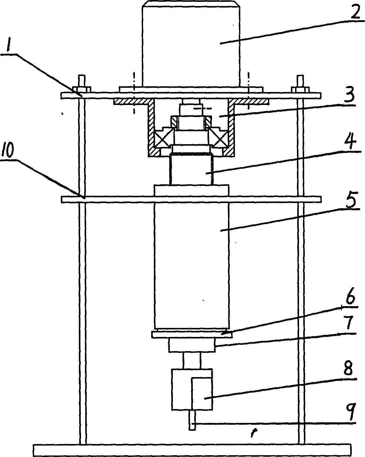
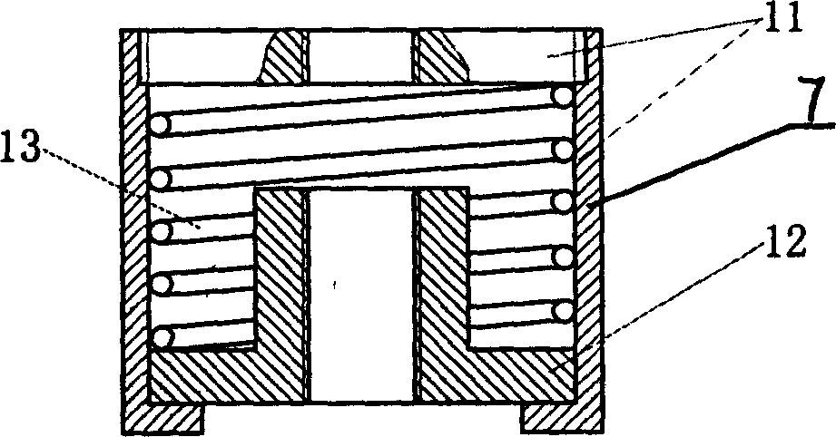
[0010] see figure 1 , the present invention comprises a frame 1 and a stepping motor 2 arranged on the upper end of the frame 1, a lead screw 4 is fixed on the shaft of the stepping motor 2, and a drive nut 5 is screwed on the lead screw 4, and the drive nut 5 is connected with the sleeve The guide plate 10 on the guide rod of the frame 1 is fixed as a whole, and the lower end of the drive nut 5 is also provided with an insulating plate 6 connected with the drive nut 5, an elastic protection device 7 and a clamp for clamping the stud 9 to be welded 8. The lead screw 4 is also covered with a protective device 3 that adopts a tapered roller bearing. Stepping motor 2 is the power part of the present invention, adopts the hybrid stepping motor that model is 57BYGH803 as drive motor, provides the required pulse si...


PUM


Abstract

The invention is a step arc stud welding gun, including frame and step machine, where there is leading screw fixed on the shaft of the step machine, the leaking screw is connected with a driving nut, the driving nut is fix together with a guide plate, and there is a clamp set at the bottom end of the driving nut. Before welding, use the welding gun to clamp the stud to place it on the workpiece surface, start up the step machine to make the driving nut to drive the clamp so as to lift the stud, at the same time, switch on the welding power supply to induce arc; when welding, make the driving nut to drive the clamp to move down so as to send the stud to the melting tank, and terminate the welding current to form welding joint. It uses step machine as power control unit so as to be able to more accurately set lift height, down feeding depth, and lift and down feeding speed for the stud, and by sampling the arc length, can implement the adjustment of are length.

Description

technical field [0001] The invention belongs to arc stud welding equipment in the field of welding technology, in particular to a step-time arc stud welding torch. Background technique [0002] Arc stud welding is a method of arc welding. During the welding process, the contacting surfaces of the stud and weldment are heated and melted by the electric arc ignited between them, and then pressed together rapidly to form the weld. The welding process can be roughly divided into five steps: 1) The welding torch clamps the stud and places it on the workpiece, and at the same time applies preload to the stud; 2) At this moment, the switch of the stud welding torch is pulled, and the electromagnetic coil in the welding torch is energized to lift stud, at the same time the welding power is turned on, and the arc is struck between the stud and the workpiece; 3) At the lifting position, the arc extends to the entire end face of the stud, and the end face of the stud is partially melt...

Claims


Application Information

Patent Timeline
IPC IPC(8): B23K9/20
Inventor 张建勋池强付继飞张友权
Owner XI AN JIAOTONG UNIV
Learn More