Antiscaling treatment and purification method for water drain pipes

A technology for drainage pipes and anti-scaling, which is applied in the directions of cleaning methods and utensils, chemical instruments and methods, cleaning hollow objects, etc. The hidden danger of blocking accidents, the difficulty of cleaning, and the effect of saving time

Inactive Publication Date: 2004-11-17
陈寿春
View PDF0 Cites 17 Cited by
  • Summary
  • Abstract
  • Description
  • Claims
  • Application Information

AI Technical Summary

Problems solved by technology

[0004] In addition, when the hardness of the water discharged from the pipeline is high, that is, when the content of calcium and magnesium salts in the water is high, a loose calcareous scaling thin layer will first be formed on the inner wall of the pipeline. At this time, an ordinary hydraulic pipe cleaner is used As time goes on, the scale layer on the inner wall of the pipeline becomes thicker and thicker, and the scale layer gradually undergoes chemical changes to form a hard scale layer with calcium carbonate and magnesium salts as the main components. At this time, hydraulic pigging is used The device has been unable to remove the fouling
[0005] After searching, no relevant reports were found about anti-scaling treatment and cleaning of drainage pipelines after installation

Method used


Image

  • Antiscaling treatment and purification method for water drain pipes
  • Antiscaling treatment and purification method for water drain pipes

Examples


Embodiment 1

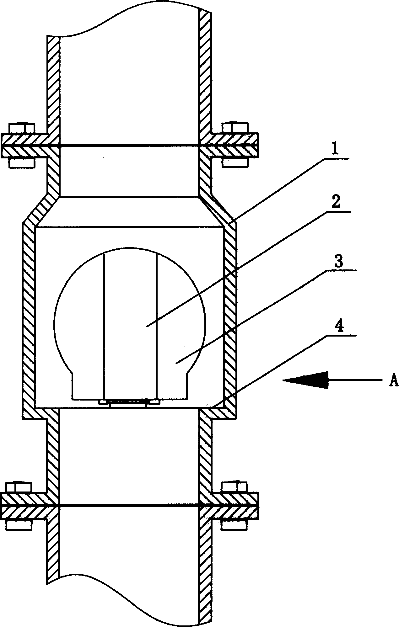
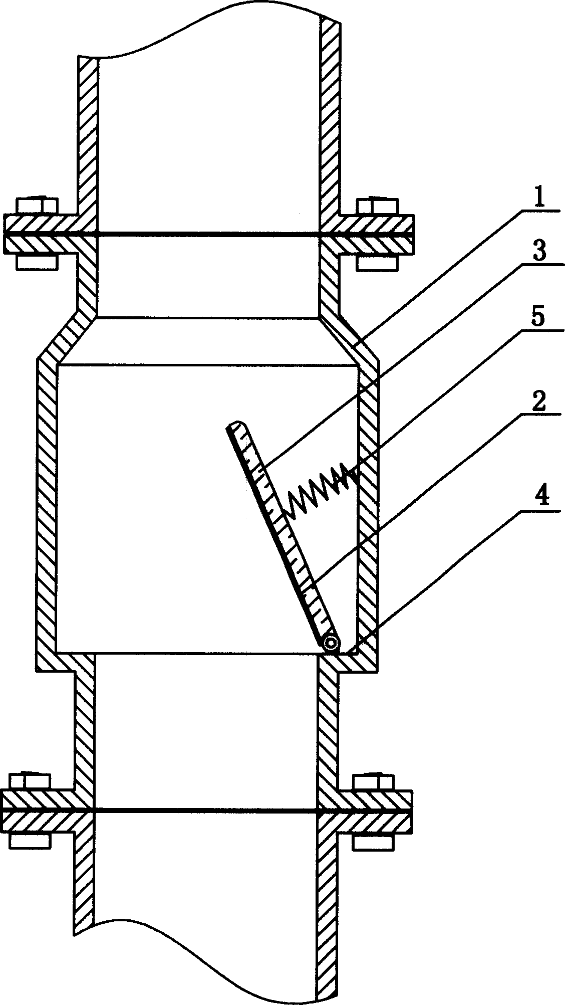
[0020] Example 1 The entrance of the lower end of the mine drainage system is a drainage pump, and then a pig launching chamber, a non-resistance check valve and a drainage pipeline are installed in sequence, as shown in the figure, the non-resistance check valve is a valve housing connected to the pipeline 1. The valve plate 3 is composed of the valve seat 4 set on the valve casing. The one-way opening valve plate is hinged on the valve seat. When the valve plate is closed, the lower end surface of the valve plate matches the valve seat. The maximum opening degree of the valve plate is 90°, the upper end surface of the valve plate is provided with a spring 5 perpendicular to the valve plate surface, the spring ensures that the valve plate returns to 70° when the opening angle reaches 90°, and an elastic spring is set on the lower end surface of the valve plate of the non-resistance check valve. Nylon protective layer2. First, use a pig to remove and clean the possible foreign...

Embodiment 2

[0021] Example 2 When the industrial drainage pipeline is installed, the lower end of the drainage pipeline is provided with a drainage pump, a pig launching chamber and a non-resistance check valve in sequence. As shown in the figure, the non-resistance check valve is composed of a valve casing connected to the pipeline 1. The valve plate 3 is composed of the valve seat 4 set on the valve casing. The one-way opening valve plate is hinged on the valve seat. When the valve plate is closed, the lower end surface of the valve plate matches the valve seat. The maximum opening degree of the valve plate is 90°, the upper end surface of the valve plate is provided with a spring 5 perpendicular to the valve plate surface, the spring ensures that the valve plate returns to 70° when the opening angle reaches 90°, and an elastic spring is set on the lower end surface of the valve plate of the non-resistance check valve. Rubber protective layer2.

[0022] The water outlet of the pipeline ...


PUM


Abstract

The invention is a contaminant preventing process and rinsing method for water discharging channels, which belongs to contaminant releasing process and rinsing technology field, the character lies in: the water discharging system includes water inlet connected by channels, discharging pump at water inlet, rinsing device ejecting barn, unresisted reverse-stop valve and water discharging channels, when the channels are assembled, uses rinsing device to eliminate the impurities in the channel at first, then carries on rinse to physical contaminant in the channels periodically, prevents the chemical contaminant from being formed. The invention reduces the affect of contaminant to water discharging process, maintains the channel expedite.

Description

technical field [0001] The invention belongs to the technical field of descaling and cleaning of drainage pipes, in particular to an antiscaling treatment and cleaning method of drainage pipes. Background technique [0002] At present, the cleaning of the liquid delivery pipeline, especially the drainage pipeline, especially the dredging of the scale adhered to the inner wall of the large-diameter and long-distance drainage pipeline has rarely been cleaned by chemical cleaning liquid and high-pressure water. The more commonly used methods are Cleaner or mechanical cleaning, such as circular thorn ball cleaners, hydraulic impeller cleaners, etc. by means of hydraulic or fluid pressure. The removal of dirt in the pipe by means of a hydraulic cleaning device has the advantages of simplicity, convenience, and cost savings, and is currently a common descaling device and method. [0003] In order not to affect the needs of normal drainage, the general descaling and cleaning work ...

Claims


Application Information

Patent Timeline
Patent Type & Authority Applications(China)
IPC IPC(8): B08B9/053
Inventor 陈寿春
Owner 陈寿春
Why Eureka
Try Eureka