Slider type universal shaft automatic lubricating device

A universal joint shaft, automatic lubrication technology, applied in the direction of engine lubrication, lubricating parts, couplings, etc., can solve the problem of the protection cover oil supply and roller replacement and inspection of the shaft connection, increase the workload of the protection sleeve, pressure spray Large oil investment and other problems, to achieve the effect of low fuel consumption, simple and compact structure, and adjustable oil volume

Inactive Publication Date: 2004-11-17
UNIV OF SCI & TECH BEIJING
View PDF0 Cites 7 Cited by
  • Summary
  • Abstract
  • Description
  • Claims
  • Application Information

AI Technical Summary

Problems solved by technology

[0004] The efficiency of manual refueling is low; the oil consumption of dripping oil is large; the investment of pressure oil injection is large and takes up space; it is difficult to chang

Method used


Image

  • Slider type universal shaft automatic lubricating device
  • Slider type universal shaft automatic lubricating device

Examples


Embodiment Construction

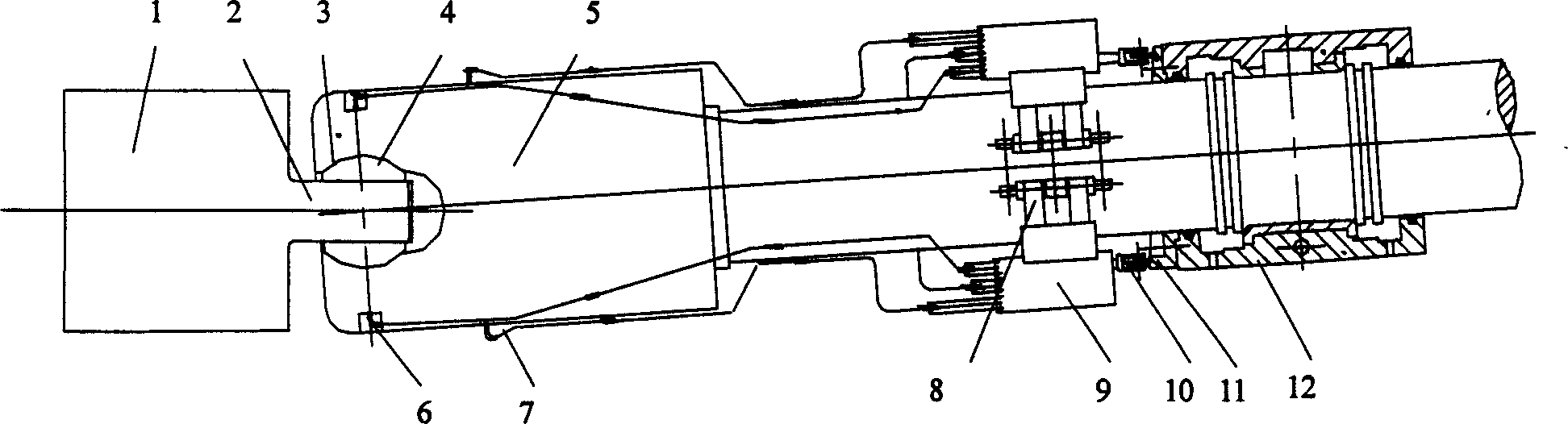
[0027] A slider type universal joint shaft automatic lubricating device, which is composed of a roll 1, a flat head 2, a tiger mouth 3, a slider 4, a universal joint shaft 5, and an oil filling hole 6, and an automatic lubrication device is designed on the universal joint shaft 5 Oil device, the oil supply device includes oil pipe 7, fixed snap ring 8, plunger pump 9, plunger pump ejector rod 10, template 11, balance support plate template 12, when connecting, plunger pump 9 is connected with fixed snap ring 8 and ten thousand It is fixed to the joint shaft 5 and rotates together with the universal joint shaft. From the plunger pump 9 to the oil filling hole 6, it is connected with the copper oil pipe 7 and then fixed on the universal joint shaft. The screw is fixed.

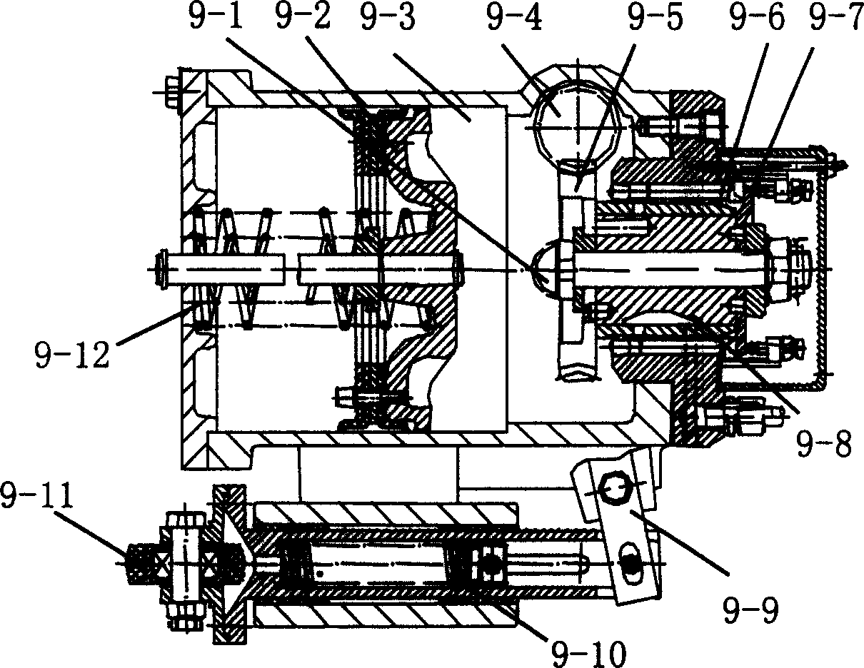
[0028] Piston pump 9 as figure 2 Shown, by filling hole 9-1, piston 9-2, oil storage cavity 9-3, worm rod 9-4, turbine 9-5, plunger 9-6, convex plate 9-7, cock 9-8, Rocking bar 9-9, return spring 9-10, roller...


PUM


Abstract

The invention is a kind of gliding block universal-joint spindle automatic lubricating device. The invention belongs to mechanical manufacturing field, especially refers to a kind of automatic lubricating device for middle board roller copper gliding block universal-joint. The device is made up of rollers, palm end, tiger's mouth, gliding block, universal-joint spindle, oil adding hole. The character lies in: there sets an automatic oil supplying device on the universal-joint spindle, the oil supplying device includes an oil pipe, a fixing clamp ring, a plunger pump, a plunger pump post rod, template, tile mold, the plunger pump is fixed with the universal-joint spindle with the fixing clamp ring, and rotates with the universal-joint spindle, from the plunger pump to the oil adding hole the invention uses copper oil pipe to connects them and fixes them on the universal-joint spindle. The template is fixed with the universal-joint spindle tile sides with screws. The structure is simple, and compact.

Description

technical field [0001] The invention belongs to the field of mechanical manufacturing, in particular to an automatic lubricating device for a universal joint shaft of a copper slider of a plate rolling mill. Background technique [0002] Recently, medium plate factories across the country have achieved remarkable economic benefits. In order to obtain greater economic benefits, all manufacturers are striving to make the rolling mill reach more than twice the designed annual output, and continue to increase production. As a result, the rolling mill load Increased size and accelerated rolling rhythm lead to extremely heavy work on the copper slider of the slider universal joint shaft. In addition to bearing a lot of pressure, friction and impact load, it is also subjected to dust, iron scale, moisture and high temperature. In such a working environment, it is extremely difficult to keep the copper slider well lubricated, resulting in poor lubrication, heat generation, and even ...

Claims


Application Information

Patent Timeline
IPC IPC(8): F16D3/16F16N7/36F16N31/00
Inventor 阎晓强杨德印
Owner UNIV OF SCI & TECH BEIJING
Why Eureka
Try Eureka