Magnet-optical disk

An optical disc, laser technology, applied in magneto-optical disc, magnetic recording, beam reproduction and other directions

Inactive Publication Date: 2004-11-17
SONY CORP
View PDF2 Cites 1 Cited by
  • Summary
  • Abstract
  • Description
  • Claims
  • Application Information

AI Technical Summary

Problems solved by technology

However, it has been found that in the above-mentioned DWDD playback method, crosstalk and crosswriting are not always the influencing factors for determining the track width, but the off-track characteristic is the main factor

Method used


Image

  • Magnet-optical disk
  • Magnet-optical disk
  • Magnet-optical disk

Examples


Embodiment Construction

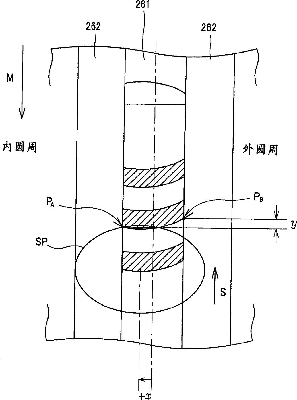
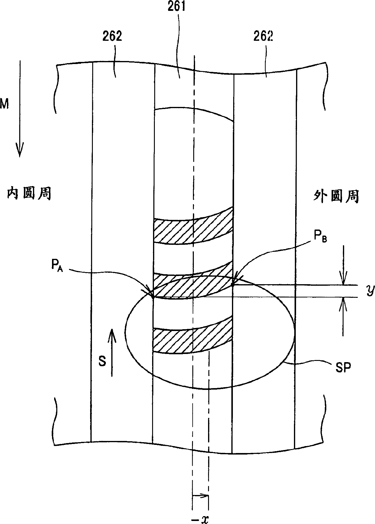
[0044] The present invention will be described in detail below in conjunction with the embodiments and accompanying drawings. This embodiment is a magneto-optical disc employing a magnetic domain wall displacement detection type ultra-high resolution reproducing method (such as a DWDD reproducing method).

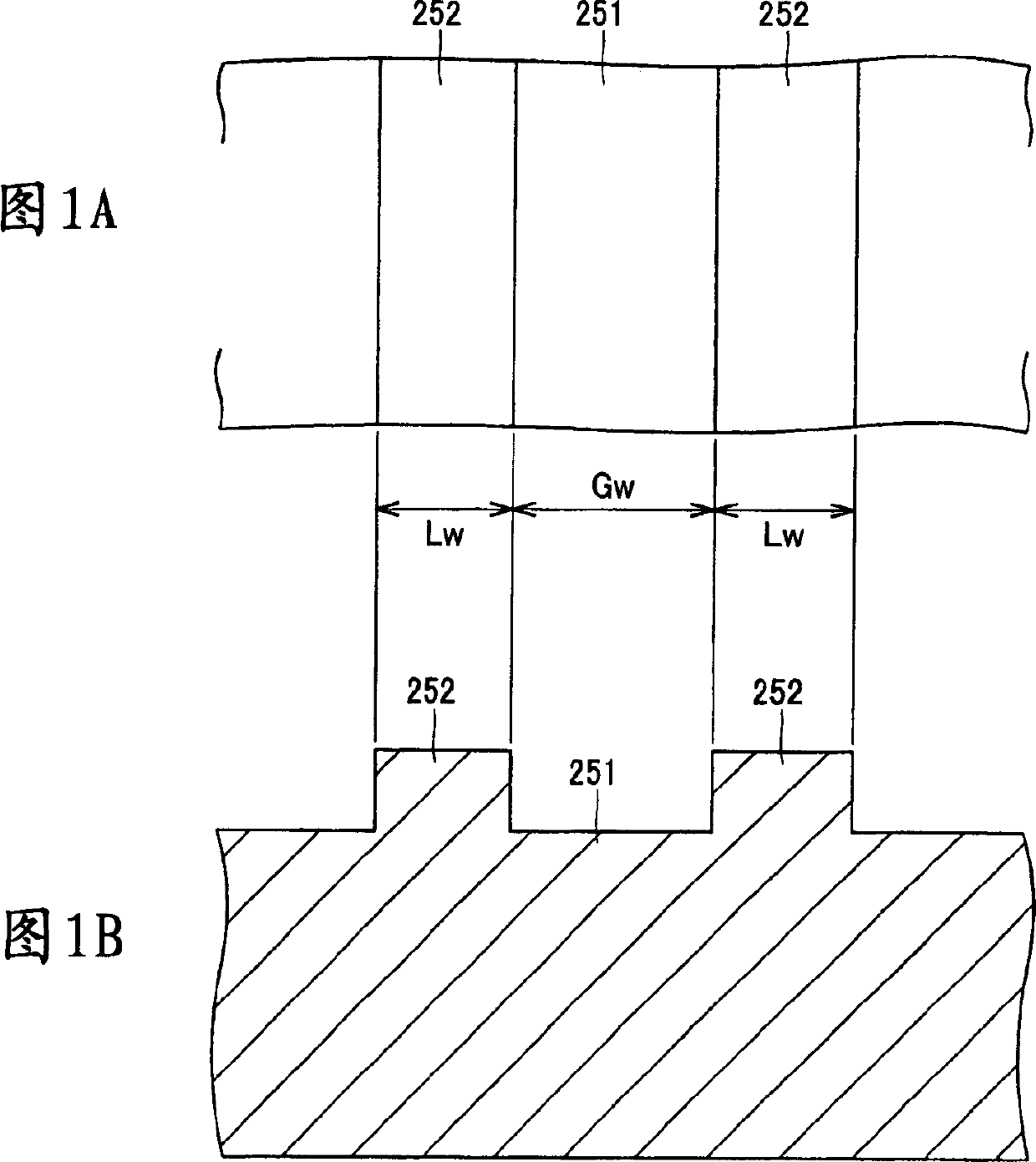
[0045]In the magneto-optical disk according to the present invention, the width Tw of the recording track satisfies the following requirements to ensure an off-track tolerance of 160 nmpp or more, which is the practical range. It should be noted that in the case of a magneto-optical disc of a groove recording type, the width Tw of the recording track is the groove width Gw, in the case of a magneto-optical disc of a planar recording type, Tw corresponds to the land width Lw, and, in the case of a magneto-optical disc of a planar In the case of the / groove recording type, both the land width Lw and the groove width Gw satisfy the following requirements.

[0046] In a disk p...


PUM

PropertyMeasurementUnit
diameteraaaaaaaaaa

Abstract

A disk reproducing device for reproducing a domain-wall-displacement type, super-resolution reproducing magnetooptic disk, wherein when the wavelength of a laser beam for reproducing signals recorded on an MO disk by being applied to the MO disk is lambda and its numerical aperture NA, the width Tw of a track provided on the MO disk satisfies Tw <= 0.046 x (lambda/NA), whereby a detrack allowance of at least 160 nmpp is ensured and designing of tracking of a disk drive is made easy.

Description

technical field [0001] The present invention relates generally to magneto-optical disks suitable for ultra-high-resolution playback of the magnetic domain wall displacement detection type, so-called DWDD (Domain Wall Displacement Detection) magneto-optical playback, and more particularly to magneto-optical disks that exhibit Magneto-optical disk with improved off-track characteristics. [0002] This patent application claims priority from Japanese Patent Application No. 2002-129311 filed April 30, 2002, the entire contents of which are hereby incorporated by reference. Background technique [0003] Magneto-optical disks are known as rewritable disk-shaped recording media. Various techniques have been developed for increasing the recording density of magneto-optical disks. For example, one such technique has recently been disclosed in Japanese Patent Application Publication No. H06-290496 (hereinafter referred to as "document 1"). [0004] The playback technology disclosed...

Claims


Application Information

Patent Timeline
Patent Type & Authority Applications(China)
IPC IPC(8): G11B7/007G11B7/09G11B11/105G11B20/12G11B20/14G11B20/18G11B27/24G11B27/30G11B27/32
CPCG11B27/24G11B20/1833G11B20/1217G11B2020/1238G11B2020/1272G11B7/24079G11B2020/1292G11B2220/235G11B20/1403G11B27/329G11B2020/1268G11B2220/2529G11B11/10578G11B2220/2525G11B7/0938G11B27/3027G11B11/105
Inventor 田中富士寺冈善之石井保渡边诚
Owner SONY CORP
Why Eureka
Try Eureka