

Machine vision inspection system and method having improved operations for increased precision inspection throughput
A technology of machine vision and inspection system, applied in the direction of instruments, image enhancement, measuring devices, etc., can solve problems such as insufficiency, and achieve the effect of avoiding time delay
- Summary
- Abstract
- Description
- Claims
- Application Information
AI Technical Summary
Problems solved by technology
Method used
Image

Examples
Embodiment Construction
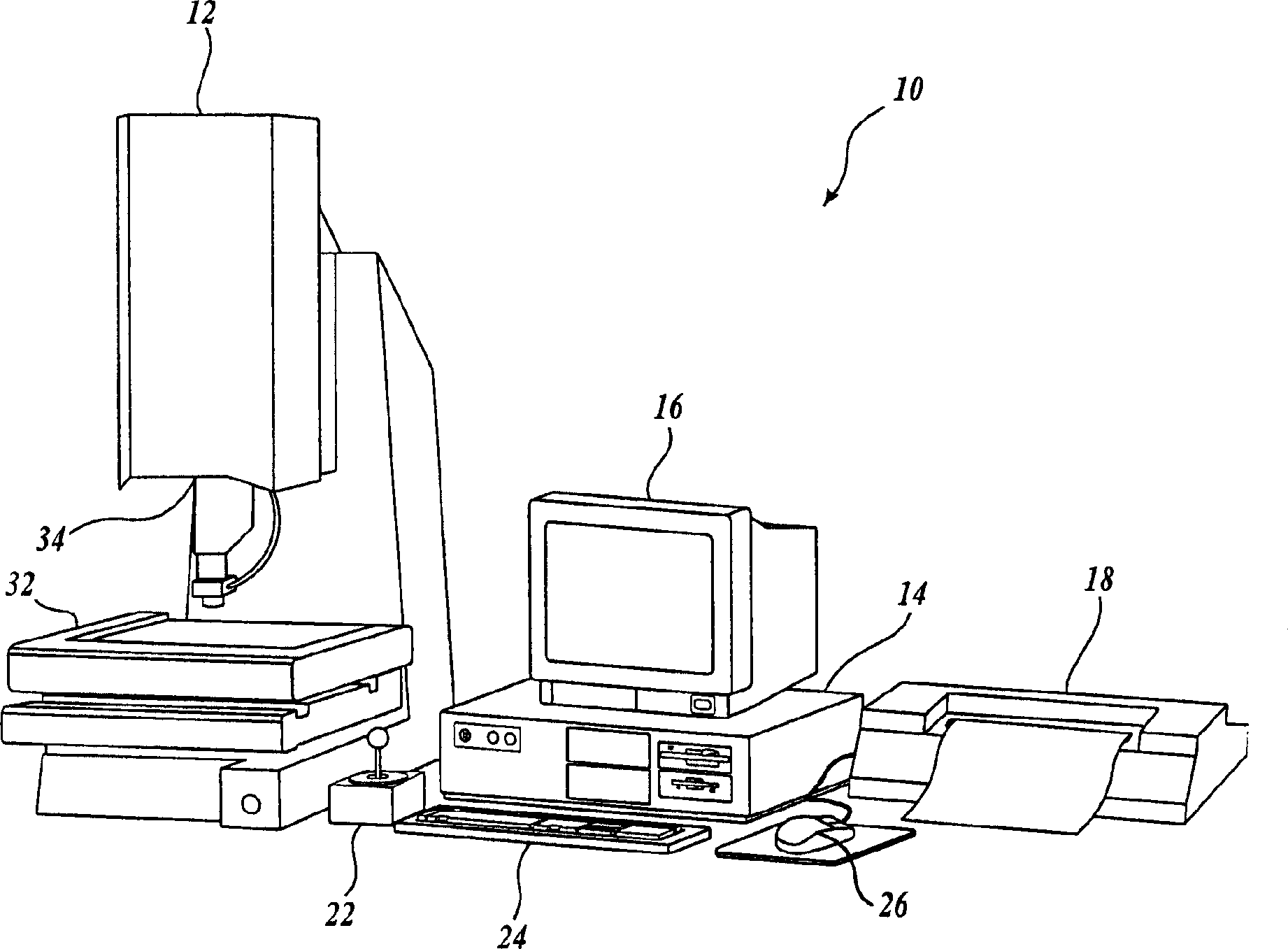
[0036] figure 1 is a block diagram of an exemplary machine vision inspection system 10 in accordance with the present invention. Machine vision inspection system 10 includes vision measurement machine 12 operably connected to and exchanges data and control signals with control computer system 14 . Control computer system 14 is also operably connected to and exchanges data and control signals with monitor 16, printer 18, joystick 22, keyboard 24, and mouse 26. Vision measurement machine 12 includes a movable workpiece measurement stage 32 and an optical imaging system 34 that may include a zoom lens or interchangeable lenses. Zoom lenses or interchangeable lenses typically provide various magnifications for the images provided by imaging optical system 34 .
[0037] The joystick 22 can typically be used to control the movement of the movable workpiece measurement stage 32 in both the X and Y directions and the directional component of the movement of the movable optical imagi...
PUM
 Abstract
Description
Claims
Application Information