Water induced laser nozzle anti-sputtering protector

A protection device, laser technology, applied in laser welding equipment, welding equipment, metal processing equipment and other directions, can solve the problems of adjustment operation of lengthy working time, water splash and water vapor filling, micro water column back splash and other problems, to prevent damage. Effect

Inactive Publication Date: 2004-12-08
崇电雷射科技股份有限公司
View PDF0 Cites 11 Cited by
  • Summary
  • Abstract
  • Description
  • Claims
  • Application Information

AI Technical Summary

Problems solved by technology

like figure 1 and figure 2 As shown, the existing water guide laser cutting machine has a serious defect, that is, in the actual operation of the water column micro nozzle 3 of the water guide laser cutting machine, due to being blocked by the part of the workpiece 8 that has not been cut through, the micro water column 4 is splashed back, resulting in Splashes and water vapor are filled below and inside the nozzle protection device 11
A large amount of moisture will inevitably condense on the surface of the nozzle guard 11 (see figure 2 ) to form the backsplash water drop 10, when the backsplash water drop 10 contacts the micro-water column, the micro-water column 4 will be pulled away from the center line, and interfere with the water column waveguid...

Method used


Image

  • Water induced laser nozzle anti-sputtering protector
  • Water induced laser nozzle anti-sputtering protector
  • Water induced laser nozzle anti-sputtering protector

Examples


Embodiment Construction

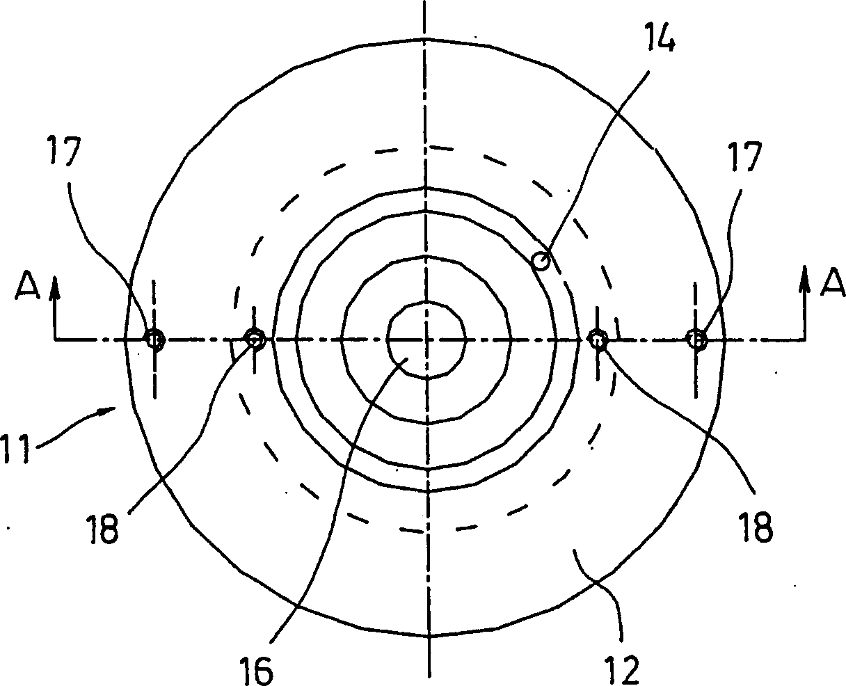
[0019] As shown in Fig. 3 (a) and Fig. 3 (b), splash guard 11 comprises a base plate 12, and a central plate 13 is surrounded by base plate 12, and the central point of central plate 13 is provided with a central penetration hole 16, in order to For the micro water column of the water guide laser cutting machine to pass through. An anti-flow groove 14 is disposed between the bottom plate 12 and the center plate 13 to prevent water droplets from flowing from the surface of the bottom plate 12 to the surface of the center plate 13 . A pair of first fixing holes 17 and a pair of second fixing holes 18 are further disposed on the bottom plate 12 , and their functions will be described in detail later.

[0020] Fig. 3(b) shows a cross-sectional view seen from the A-A plane of Fig. 3(a). As shown in Figure 3 (b), the screw is locked into the center plate 13 and connected to the base plate 12 through the second fixing hole 18, the center plate 13 is connected to a power line 15, and...


PUM


Abstract

An anti-splash protector for the water-guided laser nozzle in order to prevent said nozzle from being burnt out has a base plate fixed to the bottom of water-guided laser nozzle module and a central plate surrounded by said base plate and with a central hole for allowing the micro water column for water-guided laser to pass throught. At slot is between said both plates for preventing water drips from flowing from base plate to central plate.

Description

(1) Technical field [0001] The invention relates to a nozzle splash protection device, in particular to a water guide laser nozzle anti-splash protection device installed in a water guide laser nozzle module to protect the nozzle from being burned. (2) Background technology [0002] figure 1 and figure 2 A schematic diagram showing the structure of a water jet guided laser cutting machine in the prior art. Such as figure 1 and figure 2 As shown, the existing water guide laser cutting machine has a serious defect, that is, in the actual operation of the water column micro nozzle 3 of the water guide laser cutting machine, due to being blocked by the part of the workpiece 8 that has not been cut through, the micro water column 4 is splashed back, resulting in Splashes and moisture are filled below and inside the nozzle protection device 11 . A large amount of moisture will inevitably condense on the surface of the nozzle guard 11 (see figure 2 ) to form the backsplash...

Claims


Application Information

Patent Timeline
IPC IPC(8): B23K26/146
Inventor 江朝宗
Owner 崇电雷射科技股份有限公司
Why Eureka
Try Eureka