

Household temperature and humidity control refrigerator and controlling method thereof
A temperature and humidity control, refrigerator technology, applied in household refrigerators, household refrigeration devices, household appliances, etc., can solve the problems of food drying, poor air circulation, uncontrolled humidity, etc., to achieve easy control and ensure food preservation , control the effect of convenience
- Summary
- Abstract
- Description
- Claims
- Application Information
AI Technical Summary
Problems solved by technology
Method used
Image

Examples
Embodiment 1
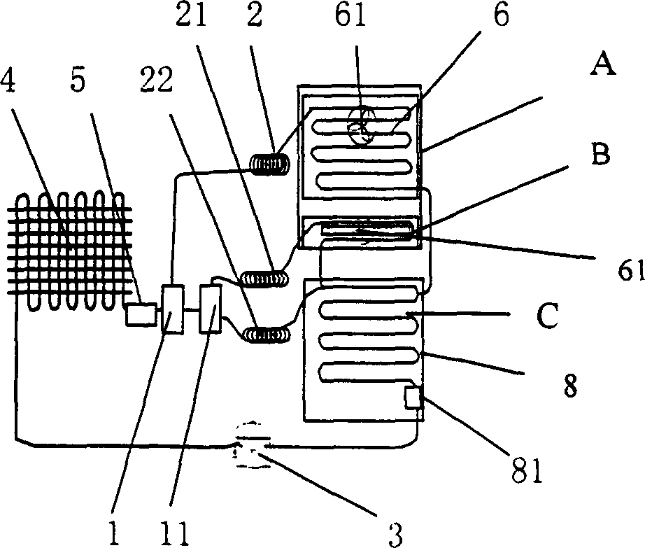
[0056] Figure 2a-Figure 2b As shown, it is a schematic structural diagram of the humidity refrigeration cycle system and the refrigeration system in Embodiment 1 of the present invention; Figure 2a As shown, one end of the compressor 3 is connected to the input end of the condenser 4, and the output of the condenser 4 is connected to the input of the first solenoid valve 1 and the first capillary tube 2 and the refrigeration evaporator 6 through a dry filter 5, and the first solenoid valve 1 The input of the humidifier and dehumidification evaporator 7 is connected through the second electromagnetic valve 11 and the second capillary tube 21, and the first electromagnetic valve 1 is connected with the input of the freezing evaporator 8 through the second electromagnetic valve 11 and the third capillary tube 22; the refrigeration evaporator 6 The output of the refrigerated evaporator 8 is connected to the input of the refrigerated evaporator 8, the output of the humidifier and...
Embodiment 2
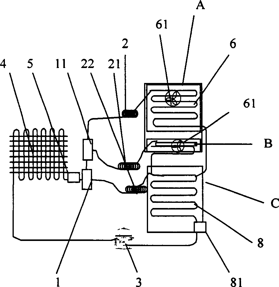
[0062] Figure 3a-Figure 3c As shown, it is a schematic structural diagram of the humidity refrigeration cycle system and the refrigeration system in Embodiment 2 of the present invention; Figure 3a As shown, one end of the compressor 3 is connected to the input end of the condenser 4, and the output of the condenser 4 is connected to the input end of the refrigerating evaporator 6 through the dry filter 5, the first solenoid valve 1, and the first capillary tube 2, and the refrigerating evaporator 6 The output end is connected to the input end of the refrigerating evaporator 8, the first electromagnetic valve 1 is connected to the input end of the refrigerating evaporator 8 through the third capillary 22, and the output of the refrigerating evaporator 8 is connected to the compressor 3 through the liquid accumulator 81;
[0063] Such as Figure 3b As shown, this structure is in Figure 3a On the basis of the change, the output of the condenser 4 is connected to the input e...
Embodiment 3
[0068] Figure 4a-Figure 4d Shown is a schematic structural diagram of the humidity refrigeration cycle system and the refrigeration system in Embodiment 3 of the present invention;
[0069] Such as Figure 4a As shown, one end of the compressor 3 is connected to the input end of the condenser 4, and the output of the condenser 4 is connected to the refrigeration evaporator 6 through the dry filter 5, the first electromagnetic valve 1, the second electromagnetic valve 11, and the first capillary tube 2. The first solenoid valve 1 is connected to the input of the humidifier and dehumidification evaporator 7 through the second solenoid valve 11 and the second capillary 21, the first solenoid valve 1 is connected to the input of the freezing evaporator 8 through the third capillary 22, and the refrigeration evaporator 6 and the output of the refrigerating evaporator 8 are connected to the compressor 3 through the liquid accumulator 81, and the outputs of the humidifier and the d...
PUM
 Abstract
Description
Claims
Application Information