
United time-space multi-path searching method and apparatus with fixed multi-beam intellectual antenna

A smart antenna, multipath search technology, applied in diversity/multi-antenna systems, antennas, antenna arrays, etc., to solve problems such as smart antenna gain reduction

Inactive Publication Date: 2004-12-08
HUAWEI TECH CO LTD
View PDF0 Cites 6 Cited by
  • Summary
  • Abstract
  • Description
  • Claims
  • Application Information

AI Technical Summary

Problems solved by technology

This increases the width of each beam and reduces the gain of the smart antenna

Method used


Image

  • United time-space multi-path searching method and apparatus with fixed multi-beam intellectual antenna
  • United time-space multi-path searching method and apparatus with fixed multi-beam intellectual antenna
  • United time-space multi-path searching method and apparatus with fixed multi-beam intellectual antenna

Examples


Embodiment Construction

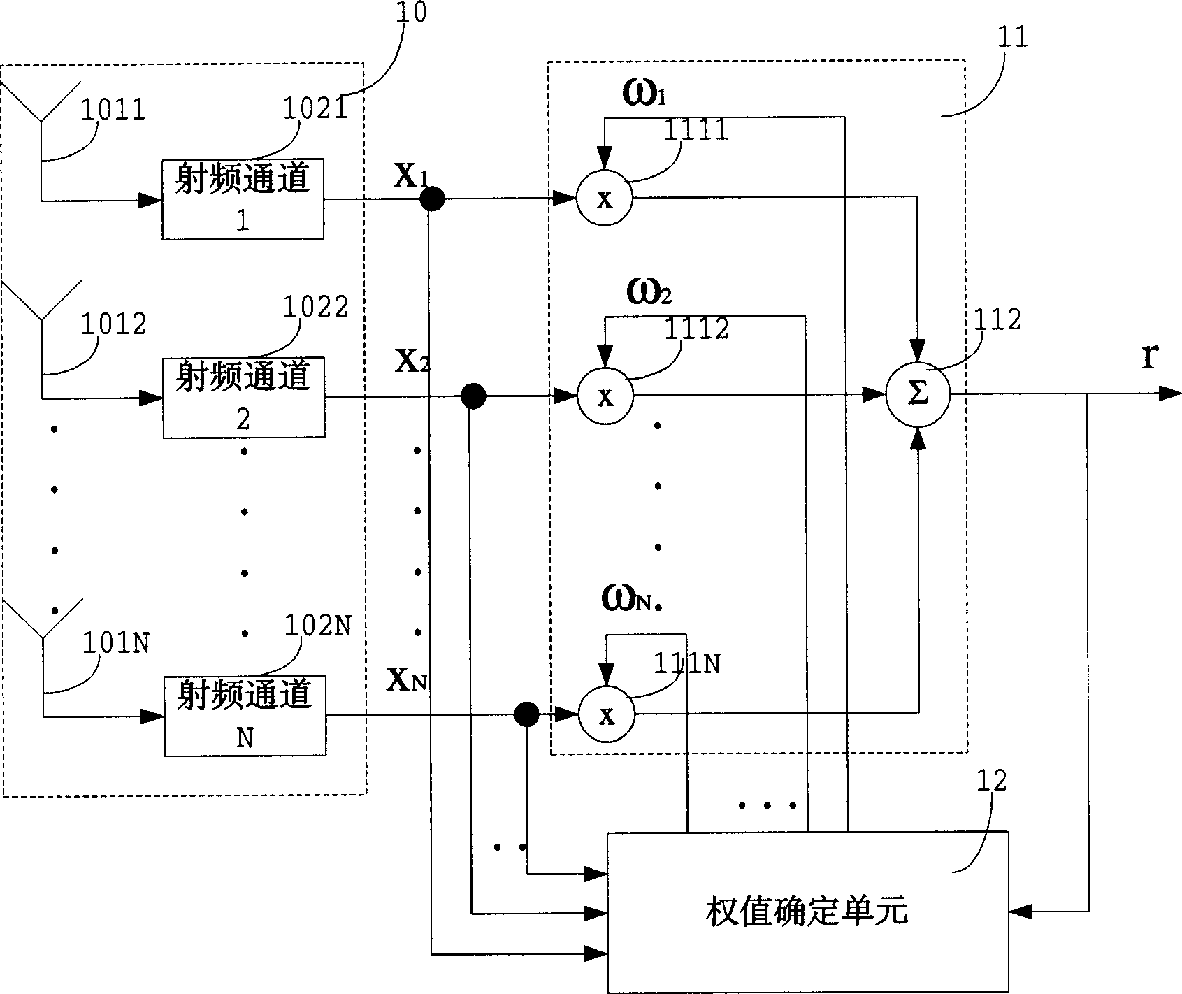
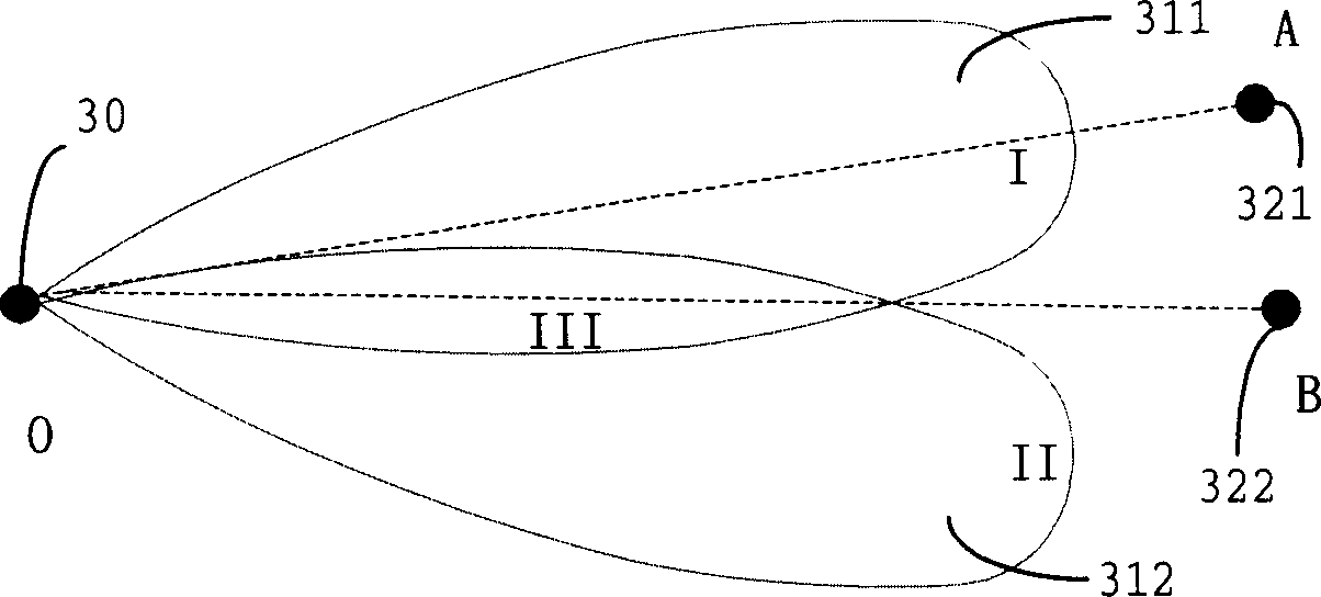
[0090] First, examine the schematic diagram of the signal arrival direction of a typical smart antenna, such as Figure 13 shown. In the figure, O is the location of the base station, and A and B are the arrival directions of two paths of a certain user respectively. The space required to receive user signals is divided into three beams 131-133. In order to ensure the consistency of the cell at each received signal angle, there is an overlapping area between the beams.

[0091] Corresponding to the three beams, the receiving strengths of multipath signals A and B are as follows: Figure 14 shown. In the figure, 141-143 correspond to the signal strength of multipath A in the three beams; similarly, 144-146 correspond to the signal strength of multipath B in the three beams. Due to the overlap between beams, multipath has a certain amount of energy in all three beams. In an actual system, due to the existence of beam side lobes and the angular spread of multipath signals, i...


PUM


Abstract

A combined space-time multi path searching method for fixed multi beam intelligent antenna and its device. It includes: the base band samples signal converting the received radio frequency signal to signal waiting to process; makes beam forming to the odd number or even numbered beam in the base sampled signal to form the beam signal; makes time delay power spectrum process to the odd number or even numbered beam to separately generate relevant time delay spectrum to each beam; adds energy gotten from all odd number or even numbered beam according to corresponding phase to get total energy corresponding to all phase; makes multi path location determine to the energy corresponding to each phase to get and outputs every multi path phase information; makes multi beam determine, according to each multi path phase information and the energy corresponded by deferent beam, confirms the numbers of the beam which the multi path is at; outputs the above beam's numbers and phase information. The invention saves N / 2 number of multi path searcher corresponding to original system.

Description

technical field [0001] The invention relates to a baseband receiving method and device for a CDMA system, in particular to a joint space-time multipath search method and device for fixed multi-beam smart antennas. Background technique [0002] The signal between the user equipment and the base station in the wireless communication system is propagated through the wireless channel. Compared with the wired channel, the nature of the wireless channel is relatively bad, and there are many interferences such as fading and multipath, so the wireless signal receiving and processing method of the wireless communication system has always been a decisive factor that directly affects the system performance. [0003] As a wireless communication system, the CDMA (Code Division Multiple Access, Code Division Multiple Access) system has the above characteristics of the wireless communication system. Moreover, since it has the characteristics of multiple users transmitting signals at the s...

Claims


Application Information

Patent Timeline
Patent Type & Authority Applications(China)
IPC IPC(8): H04B1/707H01Q21/00H04B1/10H04B7/08H04B7/26H04L25/00
Inventor 吴涛
Owner HUAWEI TECH CO LTD
Learn More