
DCT rapid changing structure

A fast, serial conversion technology, applied in image data processing, TV, color TV, etc., can solve the problems of consuming wiring resources, large circuit area, and large amount of calculation, and achieve the goals of saving wiring resources, reducing area, and improving calculation speed Effect

Inactive Publication Date: 2004-12-08
杭州高特信息技术有限公司
View PDF0 Cites 23 Cited by
  • Summary
  • Abstract
  • Description
  • Claims
  • Application Information

AI Technical Summary

Problems solved by technology

[0053] From the entire calculation process above, we can find that although the use of parity symmetry reduces the amount of calculation, but because of the use of multiple butterfly calculation structures with irregular wiring, not only the area of ​​the entire circuit is large, it consumes a lot of wiring resources, but also because Contains multiple multiplication and addition and subtraction operations, so the amount of calculation is still too large

Method used


Image

  • DCT rapid changing structure
  • DCT rapid changing structure
  • DCT rapid changing structure

Examples


Embodiment Construction

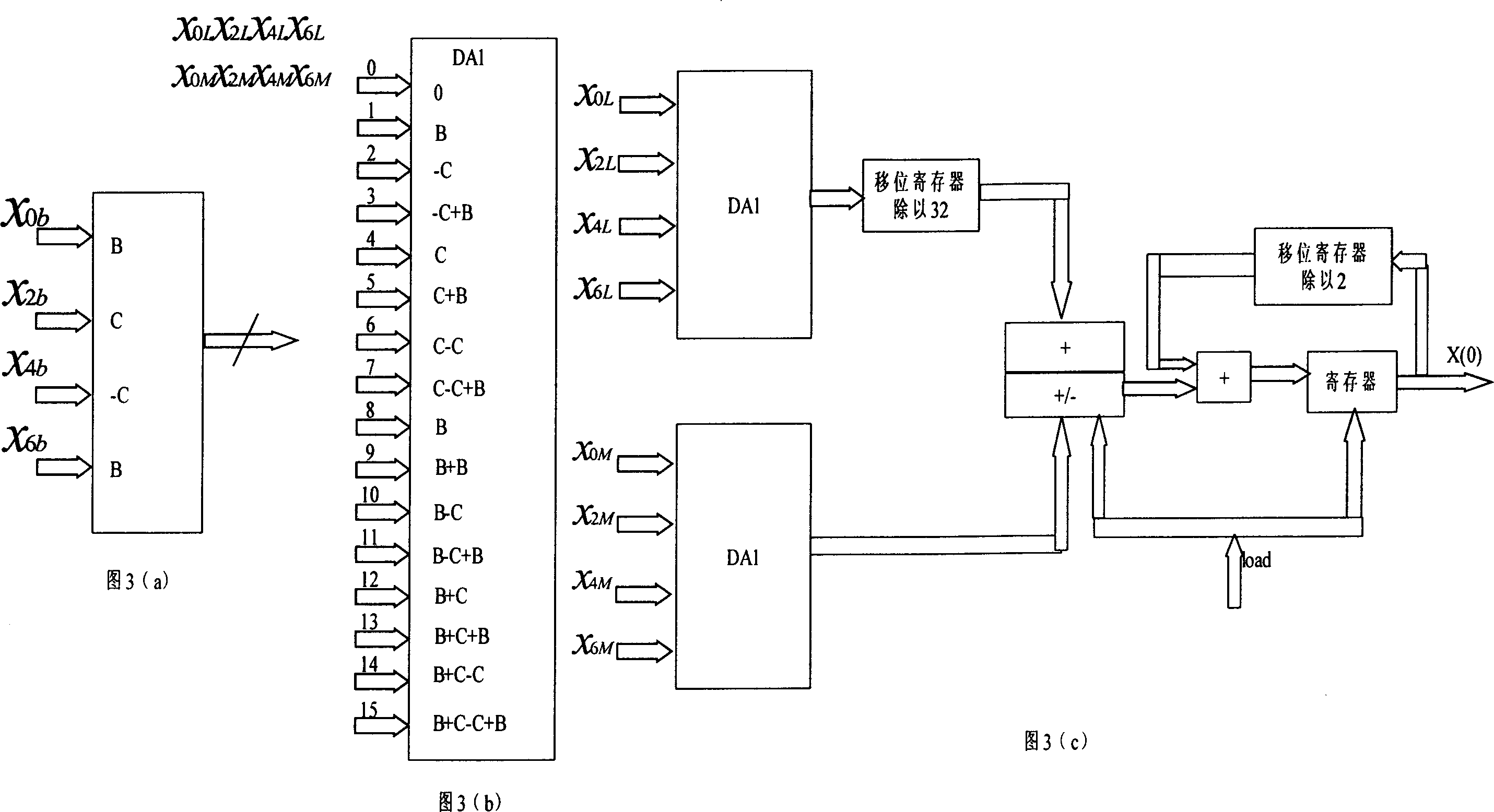
[0063] The DCT device of this embodiment takes 8×8 as a unit of image block, inputs one row or one column of image data at a time, uses table lookup operation instead of multiplication operation, and completes fast DCT transformation.

[0064] Suppose we want to implement the following formula:

[0065] y ( n ) = Σ k = 1 K A k x k ( n ) - - - - - - - ( 10 )

[0066] where A k is a constant, and x k is a variable expressed in two's complement notation. For the convenience of derivation, the x k It is limited in the range of ±1 (the actual situation does not necessarily meet this...


PUM


Abstract

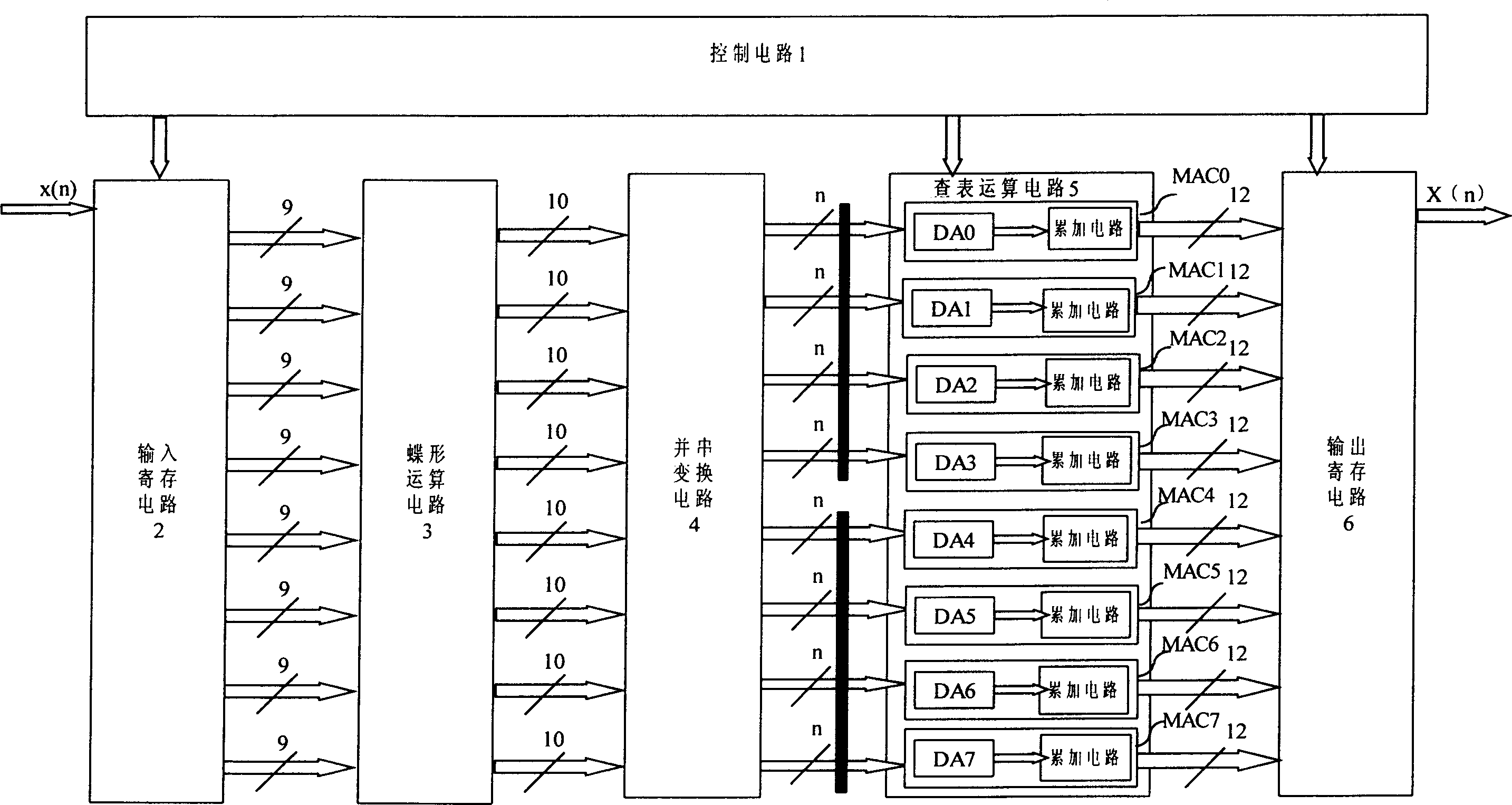
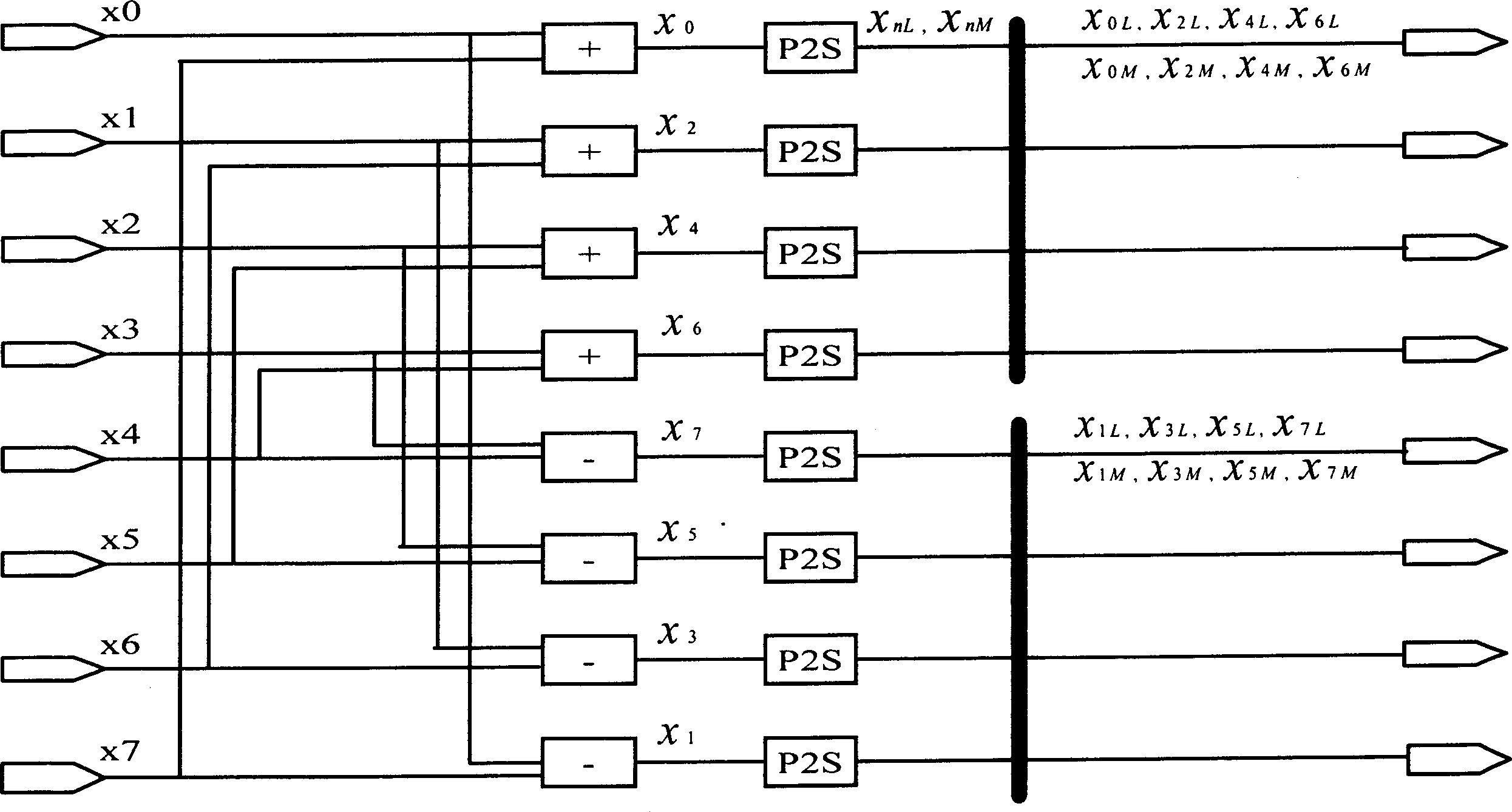
This invention provides a device for taking a two- dimensional fast DCT transform or a two -dimensional fast IDCT transform to the image data composed of 8X8 sub-block. Takes example for one dimensional DCT transform to 8X8 sub-block: the transform device comprises: the control circuit; the input deposit circuit; the butterfly operation circuit; the parallel / serial conversion circuit; table look up operation circuit; the output deposit circuit. The invention adopts the design philosophy that is to replace the multiply operation by look up table, so it need only once butterfly operation, 24 adder, 0 multiplying to complete once DCT. The design philosophy using the pipeline greatly increases the operating speed. The data can be inputted consecutively, the operation result can be gotten at each clock period. The invention is adapted to implement by using FPGA, the resource requirement saves above 30% than current structure. It can be applied in various image compression, especially in MPEG, H.26X format data that makes high requirement for the compression speed and quality.

Description

technical field [0001] The present invention relates to the FPGA-based DCT / IDCT transform structure of discrete cosine transform (hereinafter referred to as "DCT") and inverse discrete cosine transform (hereinafter referred to as "IDCT") used in information compression technologies such as image signal processing, and in particular to The image data composed of multiple 8×8 sub-blocks is subjected to two-dimensional DCT operation or two-dimensional IDCT transformation structure. Background technique [0002] With the development of microelectronics technology, the development of electronic information products has two obvious characteristics: one is the increasing complexity of products, and the other is the tight time limit for products to go to market. In response to this situation, Field Programmable Logic Devices (FPLDs) have emerged, of which Field Programmable Gate Arrays (FPGAs) and Complex Programmable Logic Devices (CPLDs) are the most widely used. [0003] Similar...

Claims


Application Information

Patent Timeline
Patent Type & Authority Applications(China)
IPC IPC(8): G06T9/00H04N5/917H04N19/423H04N19/436H04N19/625
Inventor 陈剑军
Owner 杭州高特信息技术有限公司
Learn More