Heat pipe cold guide device and cold storage body and freezer with said device

A heat pipe and cold storage technology, applied in the field of cold storage, can solve the problems of cold loss and low efficiency, and achieve the effect of less cold energy loss, simple structure and high cost performance

Inactive Publication Date: 2004-12-15
尹学军 +1
View PDF1 Cites 12 Cited by
  • Summary
  • Abstract
  • Description
  • Claims
  • Application Information

AI Technical Summary

Problems solved by technology

[0003] This kind of cold storage achieves the purpose of no commodity energy consumption, but because it uses air ducts for heat exchange, th

Method used


Image

  • Heat pipe cold guide device and cold storage body and freezer with said device
  • Heat pipe cold guide device and cold storage body and freezer with said device
  • Heat pipe cold guide device and cold storage body and freezer with said device

Examples


Embodiment 1

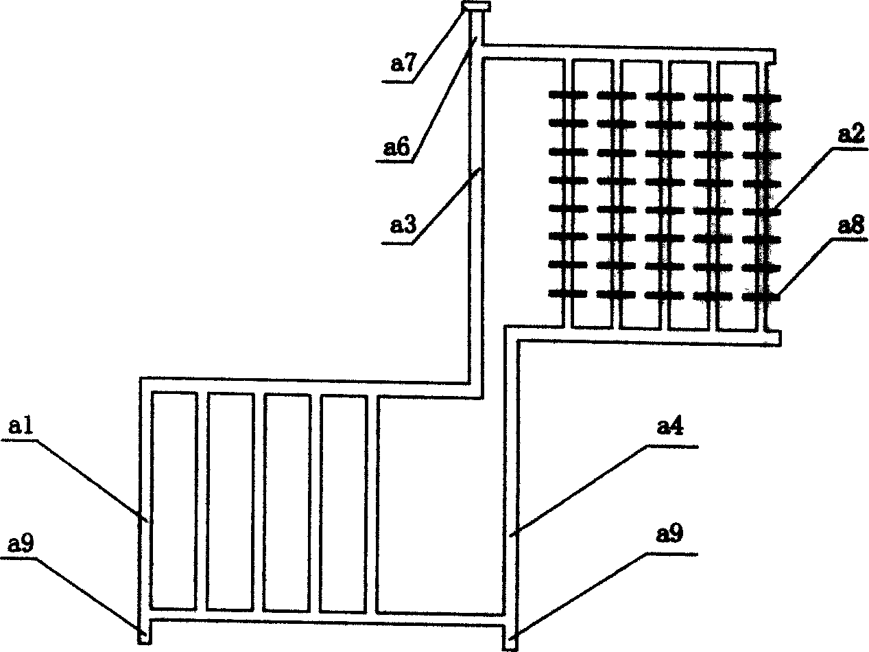
[0035] Such as figure 1 As shown, it includes the condensing tube group a2 on the upper right and the evaporating tube group a1 on the lower left. The evaporating tube group a1 includes five evaporating tubes, and the condensing tube group a2 includes five condensing tubes. The tubes in each group are respectively Connect the headers in parallel, then the upper header of the evaporating tube group and the upper header of the condensing tube group are connected through the rising pipe a3, and the lower header of the evaporating tube group is connected with the lower header of the condensing tube group through the downcomer a4, thus forming Gravity heat pipe circulation loop. In order to ensure that the working medium of the condenser tube group a2 flows back smoothly to the evaporation tube group a1, the condenser tube group a2 is higher than the evaporation tube group a1, and the lower header of the condenser tube group a2 is higher than the upper header of the evaporation tub...

Embodiment 2

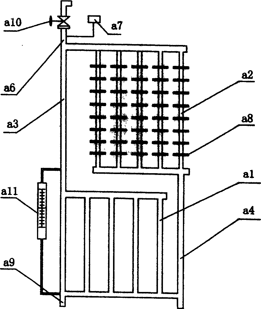
[0040] Such as figure 2 As shown, compared with Example 1, the condensing tube group a2 is located directly above the evaporating tube group a1, the riser tube a3 is provided with a communication level gauge a11, and the safety valve a7 and switch valve a10 are provided above the collecting tube a6. The on-off valve can be conveniently filled with working fluid, and the on-off valve can be opened to remove impurity gas as required.

Embodiment 3

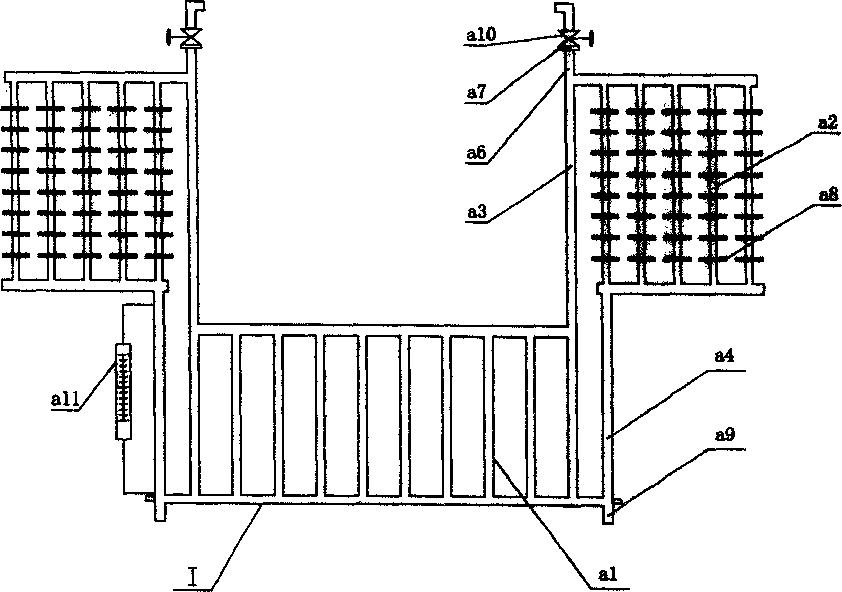
[0042] It is equivalent to the two heat pipes shown in Embodiment 1 being connected and connected symmetrically at the evaporating tube group a1. and, if Figure 4 As shown, a cooling circulation pipe a12 is concentrically passed through the lower header of the evaporating tube group a1, and a circulating working medium a13 is installed inside. A pump is set in the cooling circulation circuit to take out the cold energy in the cold storage body through circulation, so that the cold energy stored in the cold storage body can be sent to a long-distance space that needs cold energy, and the cold transmission circulation pipe can be connected with the secondary The condensing end of the heat pipe is connected in series to form an automatic circulation system of the heat pipe, and the cold energy is delivered to the evaporation end of the secondary heat pipe.

[0043] Cold storage body embodiment 1:

[0044] Such as Figure 5 As shown, it includes a cold storage medium, usually ...


PUM


Abstract

The cold-guiding heat pipe device includes at least two evaporating tubes and condensing tubes to form the evaporating tube set and the condensing tube set separately via parallel connection with the connecting tubes. The upper connecting tubes for the evaporating tube set and the upper connecting tubes for the condensing tube set are communicated, and the lower connecting tubes for the evaporating tube set and the lower connecting tubes for the condensing tube set are communicated to form the circulating loop. Inside the closed container holding cold storing medium, the evaporating tube set is soaked. The refrigerated warehouse includes heat insulator and cold storing body as the cold source. The present invention has heat pipe with high heat conductance and ring circulating loop so that it has high efficiency, high stability, low cost, low power consumption and high performance/cost ratio.

Description

technical field [0001] The invention belongs to refrigerating equipment and parts thereof, in particular to a cold conducting and heat exchanging device, a cold storage body with the cold conducting and heat exchanging device, and a cold store with the cold storage body. Background technique [0002] Most of the existing cold storage bodies and cold storages use compressors for refrigeration. However, due to this technology, it has high energy consumption, high operating costs, unstable operation, complicated maintenance operations, harmful media and noise pollution, and dependence on power engineering. Strong and other shortcomings, so people began to study refrigeration technology without power equipment. The Chinese Invention Patent Application Publication No. 91101569.8 discloses an air duct type natural cooling cold storage, a cooling device consisting of an air duct, a brine infusion tank and a cold storage body. The air pipe performs heat e...

Claims


Application Information

Patent Timeline
IPC IPC(8): F25D3/00F28D15/02
CPCF28D15/0266
Inventor 宋基盛尹学军
Owner 尹学军
Why Eureka
Try Eureka