
Passive magnetik floating permanent heart ventricle auxiliary propeller-type blood pump

A ventricular assist and permanent technology, applied in the field of medical devices, can solve the problems of increasing the volume and weight of the device, complex structure, etc., and achieve the effect of overcoming the problem

Inactive Publication Date: 2005-01-05
JIANGSU UNIV
View PDF0 Cites 11 Cited by
  • Summary
  • Abstract
  • Description
  • Claims
  • Application Information

AI Technical Summary

Problems solved by technology

[0003] The present invention aims to provide a passive maglev permanent ventricular auxiliary impeller blood pump, which overcomes the defects that the electromagnetic maglev must add electromagnets and related measurement and control systems, thus complicating the structure and increasing the volume and weight of the device

Method used


Image

  • Passive magnetik floating permanent heart ventricle auxiliary propeller-type blood pump

Examples


Embodiment Construction

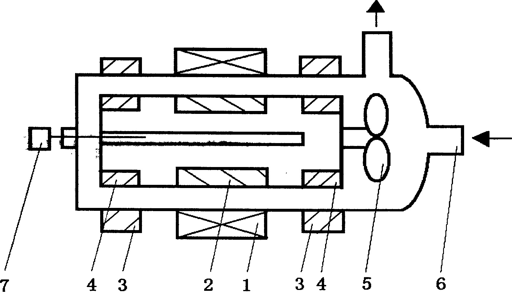
[0011] Such as figure 1 As shown, the device consists of a rotor and a stator. The coil and iron core 1 are placed in the middle of the appearance of the pump casing 6, and a large magnetic ring 3 is respectively provided at both ends to form a stator together. The rotor is composed of a drive magnet 2 located inside the pump casing 6, two small magnetic rings 4 arranged at both ends, and an impeller 5 arranged at the front end. In order to prevent coagulation and thrombus formation, saline and heparin syringes 7 are designed at the tail of the device.

[0012] When the wire coil is energized, the rotor rotates and loses contact with the stator. The impeller drives the blood to rotate and generates centrifugal force. Therefore, the blood enters the pump casing from the pump inlet and is discharged in the circumferential direction; Saline and heparin, the entire rotor will not produce coagulation and thrombus on the surface under the influence of heparin. The use of the devi...


PUM


Abstract

A permanent propeller-type blood pump for helping the failed heart is composed of rotor and stator. It features that a permanent-magnet bearing is used to realize passive magnetic floating for separating rotor from stator to avoid mechanical abrasion, and the physiological saline and heparin and directly introduced to it for avoiding blood coagulation.

Description

Technical field [0001] The invention relates to the field of medical devices, in particular to a passive maglev permanent ventricular auxiliary impeller blood pump, which is mainly used to assist a failing heart to maintain normal blood circulation. Background technique [0002] The existing permanent ventricular assist devices are all electromagnetic maglev impeller pumps, which have the advantage that there is no mechanical contact between the rotor and the stator, no mechanical friction and wear, and can be used permanently; in addition, there is no heat generated by friction problem, so no blood clots will develop. Electromagnetic maglev requires an electromagnet, as well as a rotor position measurement and feedback control system. The control system drives the electromagnet according to the measured value of the rotor position to keep the rotor separated from the stator and in a suspended state. This method not only causes the structure of the system to be complicated,...

Claims


Application Information

Patent Timeline
Patent Type & Authority Applications(China)
IPC IPC(8): A61M1/10
Inventor 钱坤喜
Owner JIANGSU UNIV
Learn More