Energy-saving control method for electro magnetic clutch of electric assisted steering device

A technology of electric power steering and electromagnetic clutch, which is applied in the direction of electric steering mechanism, etc., can solve the problems of energy waste, unfavorable energy saving and environmental protection, and achieve the effect of reducing energy consumption

Inactive Publication Date: 2005-01-05
JIANGSU UNIV
View PDF0 Cites 10 Cited by
  • Summary
  • Abstract
  • Description
  • Claims
  • Application Information

AI Technical Summary

Problems solved by technology

However, in the existing technology, the current passing through the clutch can at least ensure the transmission of the maximum assisting torque in...

Method used


Image

  • Energy-saving control method  for electro magnetic clutch of electric assisted steering device

Examples


Embodiment Construction

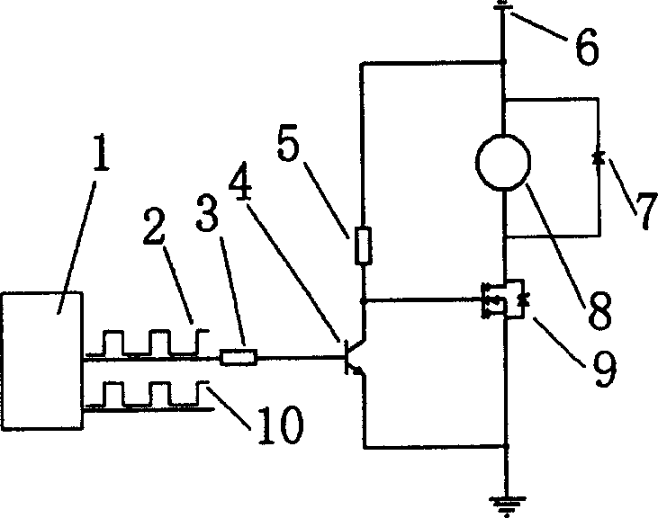
[0010] Implement an implementation of the control method, such as figure 1 As shown, the electromagnetic clutch (8) is formed by sequentially connecting a resistor (3), a triode (4), a high-power VMOS tube (9), a resistor (5) and a diode (7) connected to the two ends of the electromagnetic clutch (8) to form a loop. ) drive circuit.

[0011] During work, the PWM wave A is generated by the single-chip microcomputer (1), and the triode (4) is controlled by the resistor (3), where the resistor (3) plays the role of current limiting protection of the single-chip microcomputer (1) and the triode (4); ) The voltage signal output by the collector drives the high-power VMOS tube (9) to drive the electromagnetic clutch (8) to work, where the triode (4) plays the role of level conversion and reverses the level; in the circuit, the resistor (5) Generate sufficient control voltage as a pull-up resistor to make the high-power VMOS tube (9) work in a fully conductive state when it is turne...


PUM


Abstract

An energy-saving control method for the electromagnetic clutch of electric boosted steering mechanism features that a single-chip microprocessor in said steering mechanism is used to determine the torque to be tansferred by electromagnetic clutch according to external signals and the current needed by it. According to said current, a PWM drive signal is output and amplified to control high-power VMOS transistor, so controlling the current of electromagnetic clutch.

Description

Technical field [0001] The invention relates to an automobile electric power steering gear, in particular to an energy-saving electric power steering gear electromagnetic clutch control method, which can automatically adjust the current of the electromagnetic clutch according to different power assist conditions, so as to achieve the goals of energy saving and environmental protection. Background technique [0002] Electromagnetic clutches are often used in automobile electric power steering systems. Electromagnetic clutch has positive significance in the fault diagnosis of electric power steering and the guarantee of driving safety. In the existing electric power steering, a switch circuit is used to control the combination and separation of the electromagnetic clutch, and the control unit (ECU) of the electric power steering system controls the combination and separation of the electromagnetic clutch. When the electromagnetic clutch is turned on, the power supply voltage ...

Claims


Application Information

Patent Timeline
IPC IPC(8): B62D5/04
Inventor 何仁苗立东罗石商高高
Owner JIANGSU UNIV
Why Eureka
Try Eureka