
Atomatic fishing device

An automatic, fishing line technology, applied in fishing accessories, fishing, applications, etc., can solve the problems of fish escape from hook, increase the resistance of heavy objects, reduce the sensitivity and practicability of the device, and achieve high sensitivity and improve sensitivity. Effect

Inactive Publication Date: 2005-01-12
邓玉苓 +1
View PDF1 Cites 4 Cited by
  • Summary
  • Abstract
  • Description
  • Claims
  • Application Information

AI Technical Summary

Problems solved by technology

[0004] 1) The support frame needs to be installed in parallel. If it is not parallel, the weight will fall freely or increase the resistance of the weight to move forward, thereby reducing the sensitivity of the device;
[0005] 2) This device lifts the hooked fish out of the water, and the weight of the heavy object should not be too light. To move the heavy object forward from the rear of the parallel support frame, it must be the hooked fish or have a certain strength. It can only be done by biting the hook, which greatly reduces the sensitivity and practicality of this device;
[0006] 3) This device needs a large drop to allow the weight to drop to the position where the fish can be lifted out of the water. It is not ideal to use this device in places near water or shallow water
[0007] 4) The design of this device is to try to realize the two purposes of automatically taking the bait and automatically pulling the fish out of the water with a simple device, which makes it impossible to specialize in things.
Not very effective for both purposes
[0008] 5) This device only works when the fish bites away from the device. When the fish bites towards the fisherman, the fishing line becomes loose and the heavy objects cannot be pulled out of the parallel bracket, which may cause the fish to have Chance to unhook and escape
Being limited to unidirectionality is a problem that many automatic fishing devices cannot solve

Method used


Image

  • Atomatic fishing device
  • Atomatic fishing device
  • Atomatic fishing device

Examples


Embodiment 1

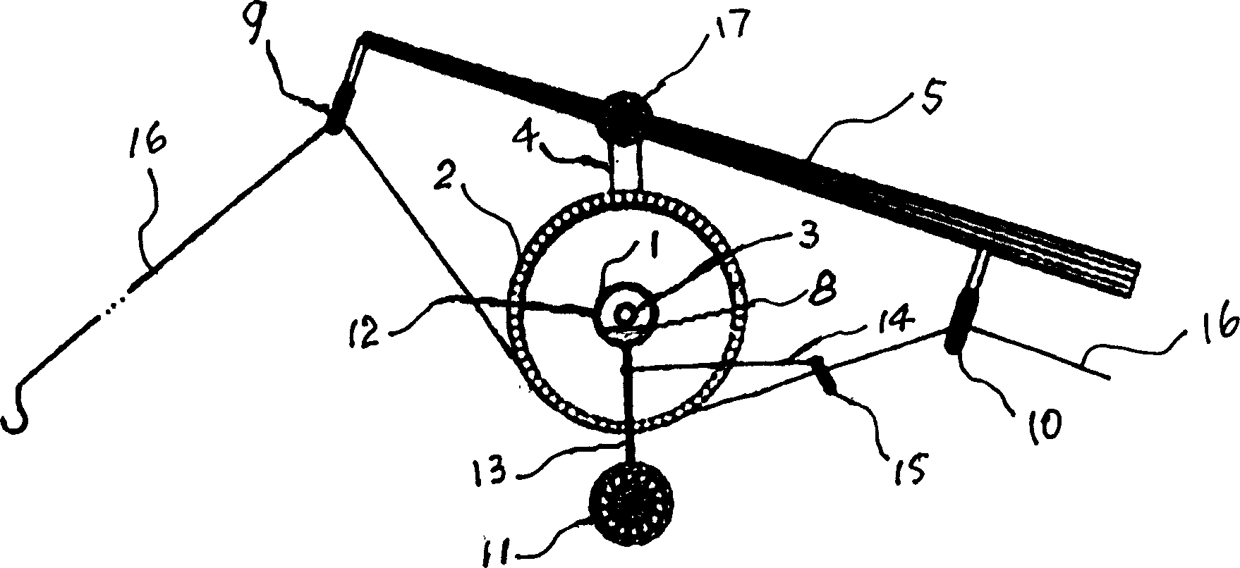
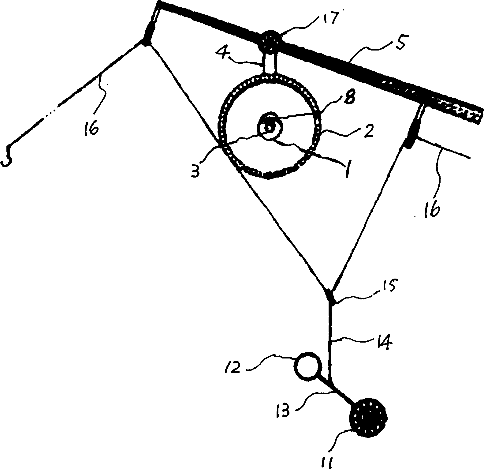
[0054] Example 1: see Figure 1-14 . The trigger is composed of a weight support body 1 and a disc-shaped fishing line support body 2. The weight support body 1 is in the shape of obliquely cutting off a part of the circumference, wherein the circumference part is provided with a weight ring groove 7 and the straight side part is a slope 8 and is smooth without grooves. The weight supporting body 1 and the fishing line supporting body 2 are both tightly connected and concentric, and the trigger rotating shaft 3 is located at the center. The radius of rotation of the fishing line support body 2 is far greater than the radius of rotation of the weight support body 1 . The outer periphery of the fishing line support body 2 is provided with a fishing line slot 6 . Rotating shaft 3 is fastened on the support by support rod 4, and this support is a short fishing rod 5. The short fishing rod 5 has only two wire loops 9 and 10, and the front part of the short fishing rod 5 is thic...

Embodiment 2

[0056] Embodiment 2: see Fig. 15, be installed on the fishing rod that guide wire loop and bobbin are top-mounted, its mode of operation is basically the same as that of embodiment 1.

Embodiment 3

[0057] Embodiment 3: See Figures 16 and 17. The weight supporting body in the trigger is made into two, i.e. parts 18 and 19, which are fastened to the two sides of the fishing line supporting body 20 respectively. The weight ring grooves on the weight supports 18 and 19 are of different lengths, making one weight support easier to allow the weight ring to slide off than the other. And the whole trigger can be placed upside down, allowing fishermen to choose to use it according to their needs.


PUM


Abstract

An automatic fishing equipment able to automatically life up hook is composed of supporting frame, trigger consisting of weight supporter and fishing string supporter, weight unit, weight string and fishing string.

Description

Technical field [0001] The invention belongs to the technical field of design and manufacture of fishing devices or appliances, in particular to a fishing device capable of automatically lifting a hook. Background technique [0002] Existing automatic fishing device or automatically make fish take the bait device, great majority is to realize with fishing rod frame. Many devices that use fishing rod holders use springs to store energy, so that when a fish bites the hook, the energy of the spring can be released suddenly to replace the manual lifting of the rod to catch the fish. The disadvantage of this type of device is mainly that the production is complicated and costly, and the weight itself is too heavy (compared to ordinary fishing rods), so it is not suitable for carrying. These disadvantages limit their practical use and market acceptance. These devices are very similar to commonly used spring-loaded mouse traps. [0003] In addition to the device using the potent...

Claims


Application Information

Patent Timeline
Patent Type & Authority Applications(China)
IPC IPC(8): A01K97/11
Inventor 邓玉苓楼恩国
Owner 邓玉苓
Learn More