Pneumatic electric car

A technology of pneumatic trams and trams, which is applied in the direction of electric vehicles, electric traction, vehicle energy storage, etc., and can solve the problems that electric vehicles cannot be well developed and popularized, the energy storage capacity of power supply batteries is small, and the driving range of batteries is limited. Achieve the effect of simple structure, power solution and low noise

Inactive Publication Date: 2005-01-12
何桥新
View PDF0 Cites 5 Cited by
  • Summary
  • Abstract
  • Description
  • Claims
  • Application Information

AI Technical Summary

Problems solved by technology

However, the most critical weak link of electric vehicles at present is the energy storage of the battery and the limitation of the driving range, especially the small energy storage of

Method used


Image

  • Pneumatic electric car
  • Pneumatic electric car
  • Pneumatic electric car

Examples


Embodiment Construction

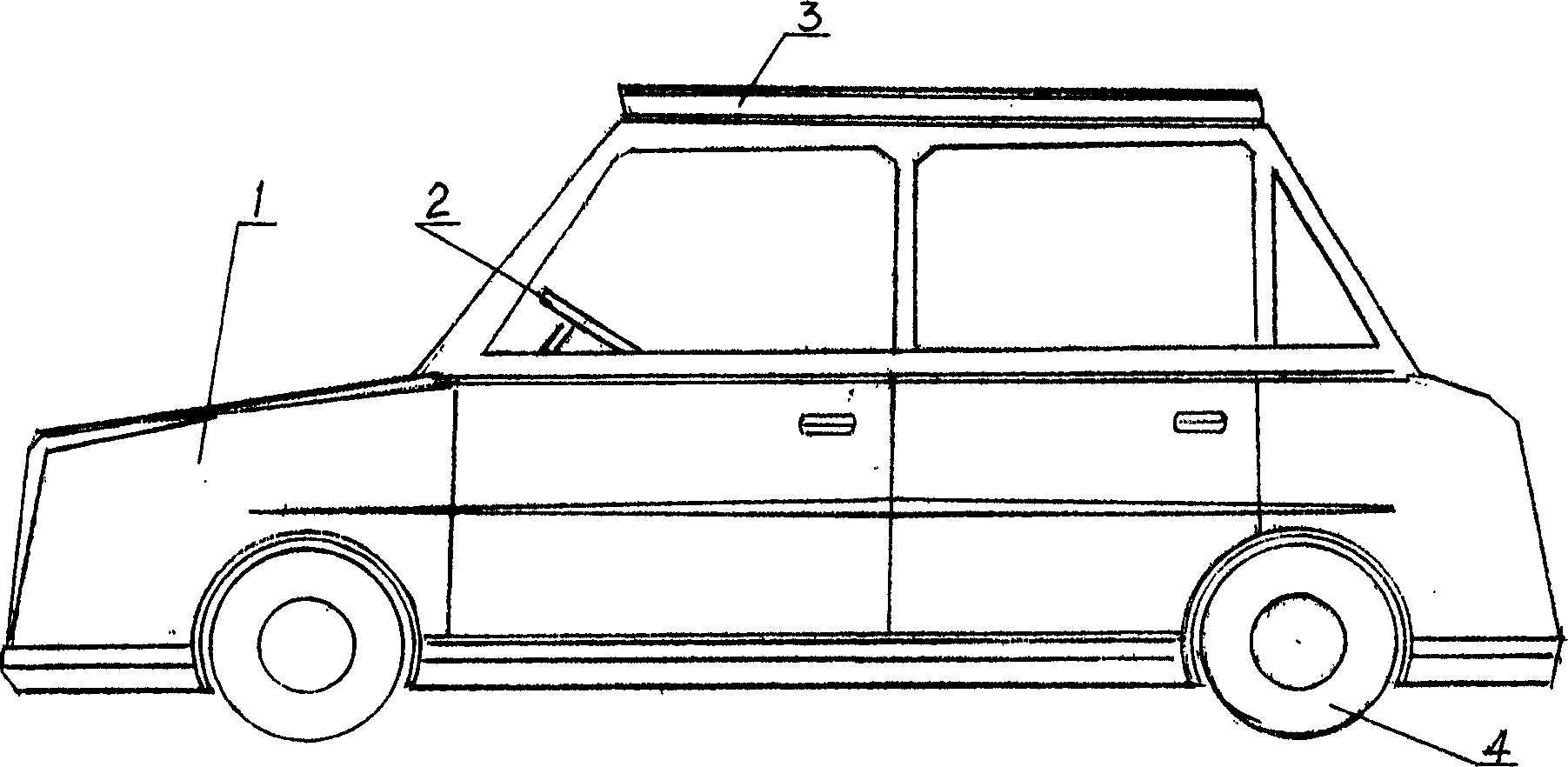
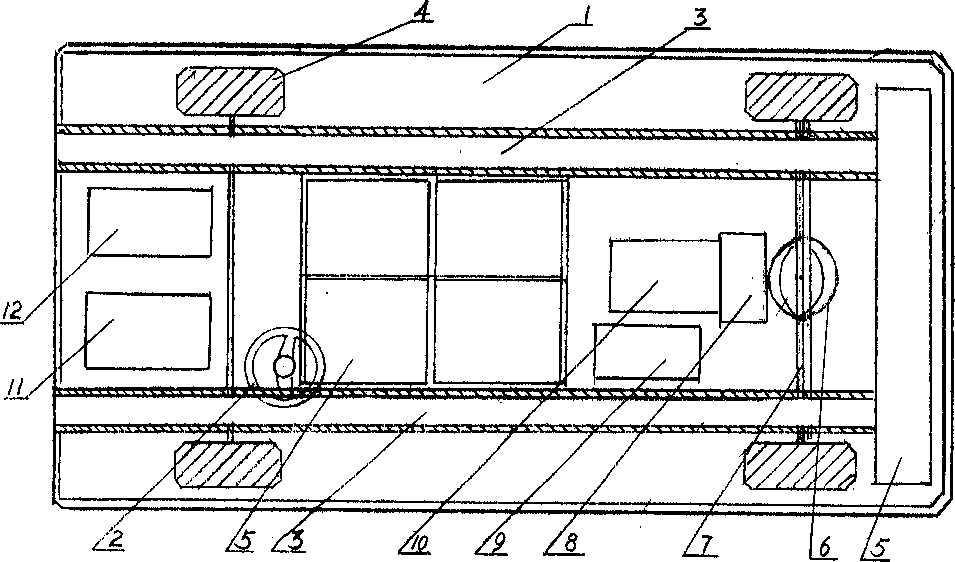
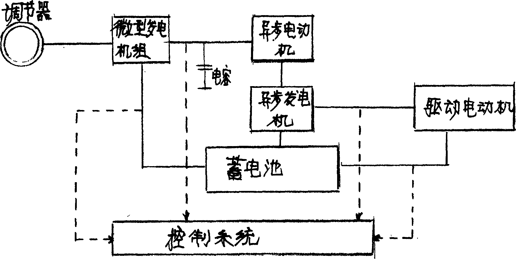
[0015] Pneumatic trams are based on the existing electric vehicles and improve the power and energy structure. The power structure is mainly composed of a micro generator set 3, a wind damper 15, an asynchronous motor 12, an asynchronous generator 11, a battery 5, a drive motor 10 and so on. Miniature wind turbines are added on the top and bottom of electric vehicles, and wind speed airflow is used as the main power source of the vehicle. The continuous movement of objects is used to convert the airflow generated at a certain movement speed into wind speed, which converts the power generated by wind energy into mechanical energy to promote wind power generation. The unit, through functions such as motors and generators, meets the power and electrical energy required for the normal operation of the vehicle. It solves the shortcomings of electric vehicles that can only be driven after a single charge and the key problem that electric vehicles cannot run continuously, so that the pne...


PUM


Abstract

An electric car using wind energy as its primary power source features that a wind-driven miniature electric generator is respectively installed to the top and bottom of car, and an automatic wind flow regulator is installed at the air inlet of said miniature elecric generator.

Description

Technical field: [0001] The invention relates to a motor vehicle, in particular to a pneumatic electric car that uses wind speed and airflow as the main power source. Background technique: [0002] With social development, human living standards and economic income continue to increase. People's purchase of motor vehicles is also increasing, and they have entered the stage of replacing vehicles with vehicles, which has promoted the rapid development of the automobile industry. Due to the increasing number of motor vehicles, the pollution of the social environment and increased noise are caused. Especially in the exhaust gas emitted by various vehicles, particles, odors and other dirt form acid rain, acid mist and photochemical smog, which are harmful to human health, crops, livestock, Huge damage to buildings, forests and natural ecosystems, destruction of ecological balance, and depletion of petroleum resources. Therefore, countries (regions) around the world are competing for r...

Claims


Application Information

Patent Timeline
IPC IPC(8): B60L8/00
CPCY02T10/7083Y02T10/7072
Inventor 何桥新
Owner 何桥新
Why Eureka
Try Eureka