

Appts. for setting up indoor water soil conservation model
A model and rain device technology, applied in soil material testing, material inspection products, etc., can solve problems such as cost increase, and achieve the effects of uniform raindrops, easy installation and cost saving
- Summary
- Abstract
- Description
- Claims
- Application Information
AI Technical Summary
Problems solved by technology
Method used
Image

Examples
Embodiment Construction
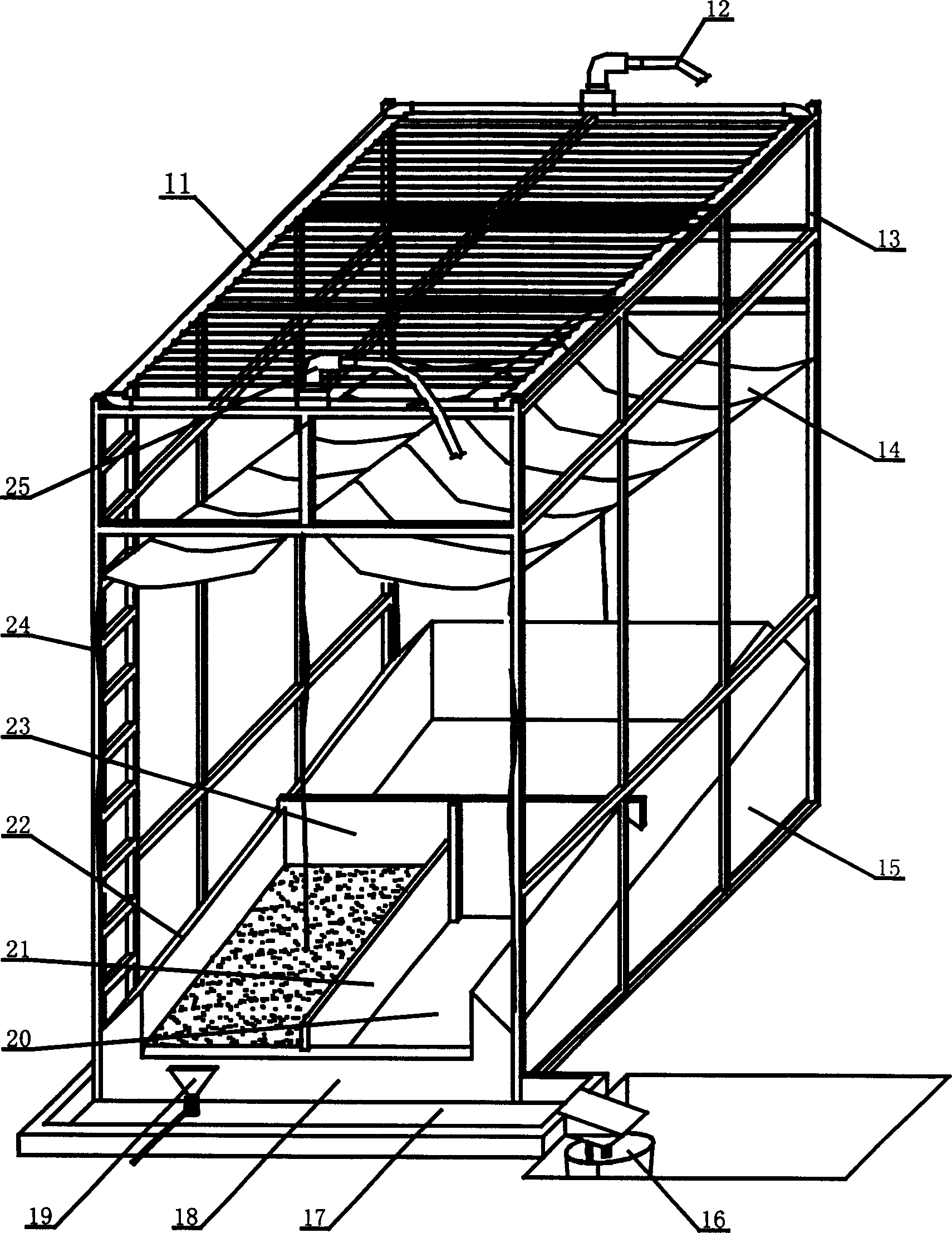
[0019] The device proposed by the present invention for establishing an indoor soil and water conservation model has a structure such as image 3 As shown, it includes a rainfall device 11, an awning 14, an underlying surface model 15, a sampler 19 and a runoff bucket 16. The rainfall device 11 is placed on the top of the support 13, the rain shield 14 is placed in the middle of the support 13, and the underlying surface model 15 is placed at the bottom of the support 13. Rainfall device 11 is made up of main pipe 26 and branch pipe 27, and main pipe is square, and a plurality of branch pipes are arranged in parallel in main pipe, and main pipe and branch pipe communicate with each other. One side of the main pipe 26 is provided with a water inlet pipe 12 , and the opposite side is provided with a sewage discharge pipe 25 . The underlying surface model 15 includes a slope 20, a side wall, a movable side partition 21 and a movable rear partition 23, the slope 20 is the bottom ...
PUM
 Abstract
Description
Claims
Application Information