Double-refraction microstructure optical fiber and its mfg. method

A micro-structured optical fiber and birefringence technology, applied in the direction of light guides, optics, optical components, etc., can solve problems such as limitations and inability to propagate light waves, and achieve the effects of low cost, good polarization temperature stability, and high birefringence performance

Active Publication Date: 2005-01-12
FENGHUO COMM SCI & TECH CO LTD
View PDF0 Cites 18 Cited by
  • Summary
  • Abstract
  • Description
  • Claims
  • Application Information

AI Technical Summary

Problems solved by technology

The period of change of the refractive index of the periodically arranged material is the order of the wavelength of light. There are medium defects in the periodically arranged medium. Due to the influence of PBG, there is a band gap effect on the wavelength of a certain band

Method used


Image

  • Double-refraction microstructure optical fiber and its mfg. method
  • Double-refraction microstructure optical fiber and its mfg. method
  • Double-refraction microstructure optical fiber and its mfg. method

Examples


Embodiment Construction

[0040] The structure and manufacturing method of the birefringent microstructure optical fiber of the present invention will be explained in detail below in conjunction with the accompanying drawings.

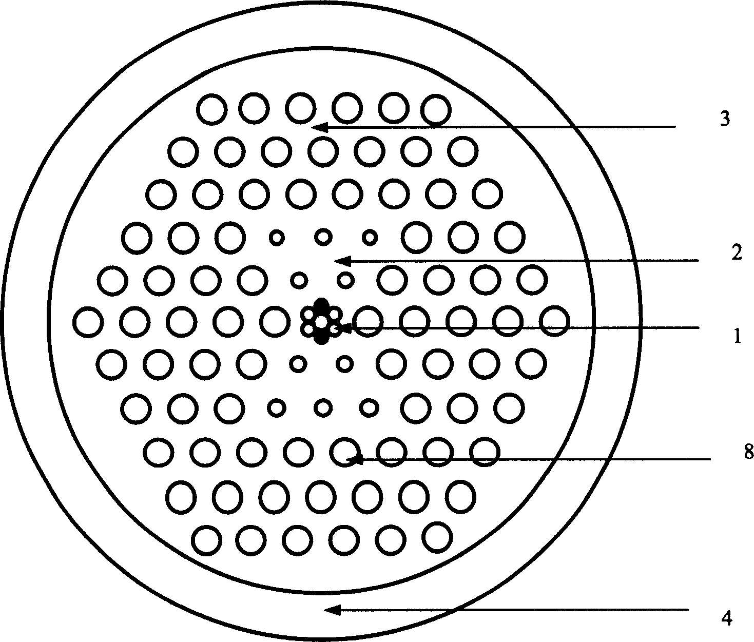
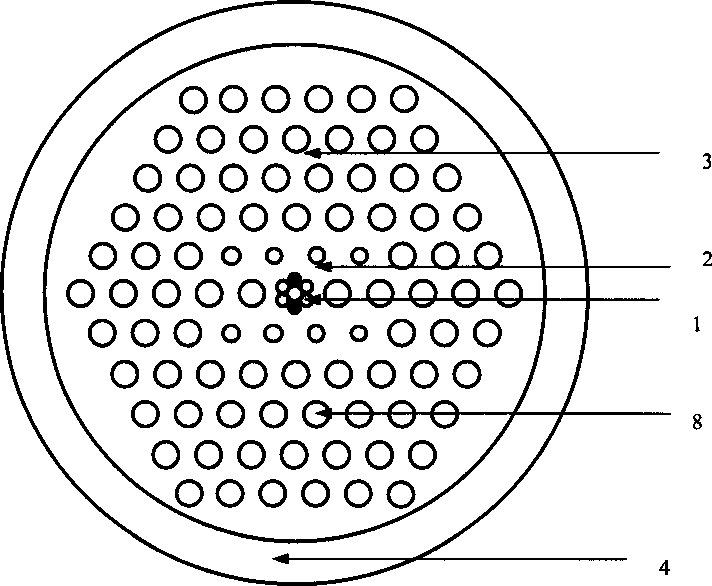
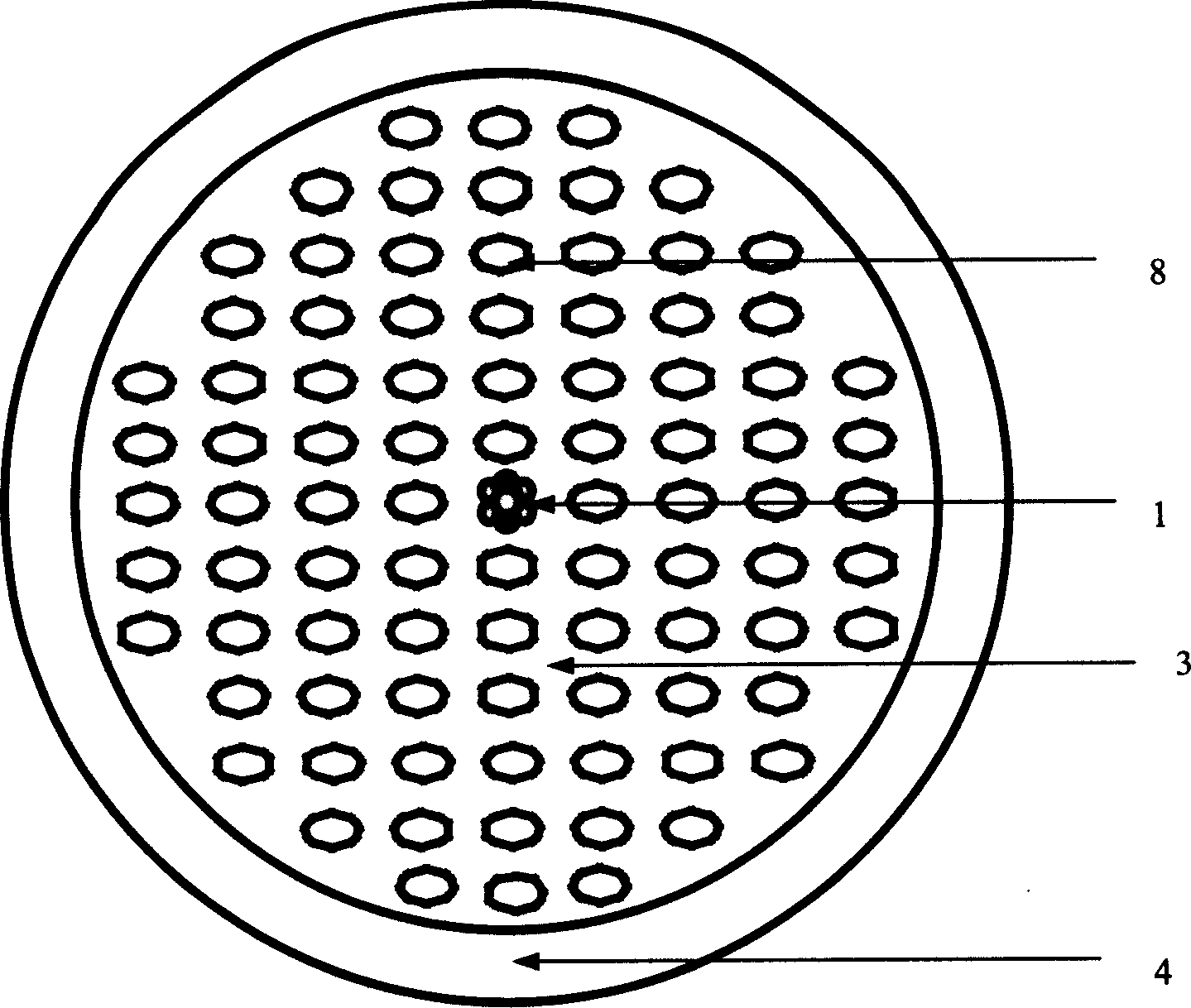
[0041] figure 1 It is a cross-sectional schematic diagram of an optical fiber with a "figure-eight" birefringence microstructure. The fiber is composed of an inner region 1 surrounding the core, and microholes with smaller diameters form a cladding region 2 of a "figure-eight" structure. The circle The cladding area 3 is composed of a hexagonal array of micro-holes arranged in a hexagonal structure, and an optical fiber coating area 4 composed of an organic polymer, and the micro-holes 8 in the cladding are approximately circular. The micropore diameter in the cladding region 2 is smaller than that in the cladding region 3, and the distribution along the axial direction perpendicular to each other of the optical fibers presents a "figure-eight" distribution, so it is effective ...


PUM


Abstract

The fiber includes central core area, cladding area and coating area. Cladding area includes buried micropore array in axial direction surrounding the core area and coating area. Changing shapes, structures, size and quantity and arrangement etc. forms major effective refractivity between two perpendicular directions in fiber so as to fabricate birefringence microstructure optical fiber. Fabricating method includes steps: preparing pure or doping quartz tiny stick and pure quartz tiny tube with certain wall thickness; fabricating the said sticks and tubes to specific shape; assembling the said sticks and tubes to desired shape; bundling sticks and tubes in quartz sleeve; fiber drawing forms optical fiber.

Description

technical field [0001] The invention relates to a microstructure optical fiber and a manufacturing method thereof, in particular to a microstructure optical fiber with birefringence performance and a manufacturing method thereof. Background technique [0002] Micro-structured optical fiber (MOF) refers to an optical fiber with a certain diameter and a certain number of microholes distributed in the cladding and (or) core of the fiber. The microholes are parallel to the central axis of the fiber and run through the entire fiber. When the arrangement of regular microholes on the cross-section of the fiber has a two-dimensional periodic structure and remains basically unchanged in the third dimension (the axis of the fiber), the refractive index of the cross-section of the fiber presents a two-dimensional periodic structure. The novel structural fiber with this characteristic is also called Photonic Crystal Fiber (Photonic Crystal Fiber). [0003] According to the principle of...

Claims


Application Information

Patent Timeline
IPC IPC(8): C03C25/00
Inventor 陈伟李进延李诗愈李海清蒋作文刘学军刘革胜
Owner FENGHUO COMM SCI & TECH CO LTD
Why Eureka
Try Eureka