A low-loss terahertz polarizing beam splitter

A polarizing beam splitter and terahertz technology, applied in the direction of instruments, light guides, optics, etc., can solve the problems of weak y-polarization mode coupling, poor effective refractive index, and difficult production, so as to reduce device loss and absorption loss , The effect of device loss reduction

Active Publication Date: 2019-11-19
JIANGXI NORMAL UNIV
View PDF4 Cites 0 Cited by
  • Summary
  • Abstract
  • Description
  • Claims
  • Application Information

AI Technical Summary

Problems solved by technology

When the fiber length is equal to a coupling length of the x polarization mode, the two polarization modes are effectively separated, and the length of the polarization beam splitter is only a coupling length of the x polarization mode. In order to prevent the mode fields of the y polarization mode from overlapping, the distance between the two fiber cores It must be large enough, the coupling length of the x-polarization mode cannot be effectively reduced, and the transmission loss of the polarization beam splitter is still relatively high
[Hongzhi Chen et al., "Terahertzpolarization splitters based on total and partial coupling in dual slottedcore polymer fiber:comparison and analysis," IEEE Photonics Journal, 2017, 9,7103315] proposed asymmetric dual slotted core polymer fiber Core polarization beam splitter, the fundamental mode of each core has high birefringence characteristics, by adjusting the structural parameters, at the same frequency, the effective refractive index of the x-polarized mode of the two cores is equal, and the effective refractive index of the y-polarized mode There is a large difference in the rate, the x polarization mode can be completely coupled between the two cores, the y polarization mode is weakly coupled, the length of the polarization beam splitter is a coupling length of the x polarization mode, and the length of the polarization beam splitter can be reduced It is 1cm, effectively reducing the transmission loss of the polarized beam splitter, but the structure of the beam splitter is more complicated, and it is more difficult to manufacture

Method used


Image

  • A low-loss terahertz polarizing beam splitter
  • A low-loss terahertz polarizing beam splitter
  • A low-loss terahertz polarizing beam splitter

Examples


Embodiment 1

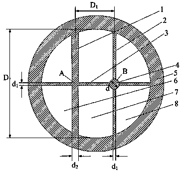
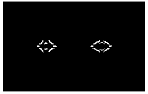
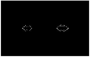
[0023] The low-loss terahertz polarizing beam splitter structure of the present invention (such as figure 1 shown), air refractive index nair =1.0, the matrix material of the optical fiber is selected as cycloolefin copolymer Topas, its refractive index n=1.5258, the thickness d of the first dielectric layer 2 and the third dielectric layer 3 1 =30μm, the thickness d of the second dielectric layer 1 2 =50 μm, the inner diameter of the dielectric circular tube 5 is D=5000 μm, the thickness of the dielectric circular tube 5 is 500 μm, and the distance between the first core A and the second core B is D 1 . in D 1 =600μm, figure 2 , image 3 , Figure 4 and Figure 5 The electric field intensity distribution diagrams of the x-polarized odd supermode, x-polarized coupled supermode, y-polarized odd supermode and y-polarized coupled supermode are given respectively. It can be seen from the figure that the x-polarized odd supermode and coupled supermode can are coupled to eac...


PUM


Abstract

The invention discloses a low-loss terahertz polarization beam splitter, in which the first dielectric layer and the second dielectric layer are longitudinally spaced apart, and the third dielectric layer perpendicularly intersects the first dielectric layer and the second dielectric layer, wherein the first dielectric layer The intersection of the three dielectric layers and the first dielectric layer constitutes the first fiber core; the intersection of the third dielectric layer and the second dielectric layer is suspended with a dielectric cylinder; the third dielectric layer passes through the center of the medium tube and both ends are connected to the medium tube The inner wall of the tube is fixedly connected, and the two ends of the first dielectric layer and the second dielectric layer are fixedly connected with the inner wall of the dielectric tube, and the whole is a total internal reflection structure. The invention effectively reduces the material absorption loss, effectively shortens the length of the polarization beam splitter, and reduces the device loss of the polarization beam splitter.

Description

technical field [0001] The invention relates to a terahertz coupling device, which belongs to the technical field of optical fiber communication, in particular to a low-loss terahertz polarization beam splitter. Background technique [0002] Terahertz (THz) usually refers to electromagnetic waves with a frequency in the range of 0.1 to 10 THz, and its band is between microwave and infrared in the electromagnetic spectrum. THz radiation has potential applications in many fields, such as communication, sensing, imaging, spectroscopy, and medicine. The whole THz system generally consists of three main parts: THz radiation source, optical waveguide and detector. At present, THz radiation sources and detectors are getting closer and closer to practicality, but THz optical fibers and devices are still in the stage of theoretical and laboratory research, because the low-loss transparent materials used to form optical fibers and optical fiber devices required in this band are relat...

Claims


Application Information

Patent Timeline
Patent Type & Authority Patents(China)
IPC IPC(8): G02B6/126G02B27/28
Inventor 祝远锋刘鑫钟华饶春芳
Owner JIANGXI NORMAL UNIV
Why Eureka
Try Eureka