
Jet nozzle structure of sand ejector

A sandblasting machine and nozzle technology, applied in the direction of spray guns, explosion generating devices, abrasives, etc., can solve problems such as inconsistent directions, reduced effect of etching PDP panels, and lateral etching

Inactive Publication Date: 2005-01-19
AU OPTRONICS CORP
View PDF0 Cites 10 Cited by
  • Summary
  • Abstract
  • Description
  • Claims
  • Application Information

AI Technical Summary

Problems solved by technology

Because the nozzle 12 is a long and narrow rectangular shape, the direction of the abrasive material output from the slit 13 is not consistent enough, that is, part of the abrasive material will be sprayed outwards instead of vertically downwards, which will cause the effect of etching the PDP panel to be reduced, and Will cause more serious side etching

Method used


Image

  • Jet nozzle structure of sand ejector
  • Jet nozzle structure of sand ejector
  • Jet nozzle structure of sand ejector

Examples


Embodiment Construction

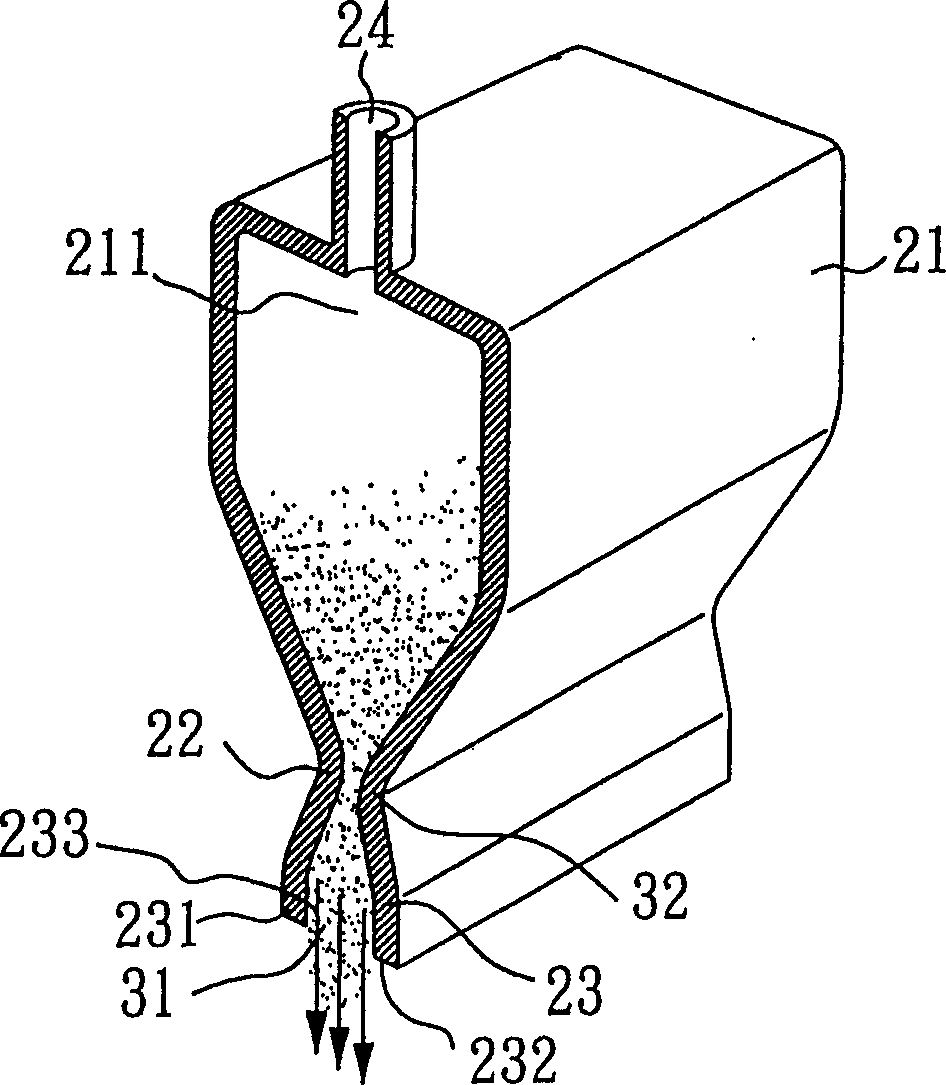
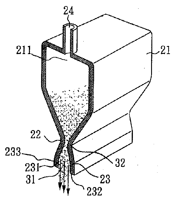
[0010] For preferred embodiments of the present invention, please refer to figure 2 The schematic diagram of the nozzle structure shown mainly includes an input part 21, a throat part 22 and an output part 23, wherein the throat part 22 is formed by extending the bottom end of the input part 21, and the output end 23 is formed by extending the bottom end of the throat part 22. The output end 23 includes a first output wall 231 and a second output wall 232, the first output wall 231 and the second output wall 232 are flat, and there is an output channel 31 between the first output wall 231 and the second output wall 232 . In this embodiment, the shape of the input portion 21 is wide at the top and narrow at the bottom, so that the throat 22 extending from the bottom of the input portion 21 has a narrow channel 32 .

[0011] The above-mentioned input part 21 is connected with a conveying pipe 24 with an input port 211, so that the grinding material (sand material) provided by ...


PUM


Abstract

The invention provides a jet nozzle for a sand blasting machine comprising an input part, a throat part, and an output part. The input part communicates with a delivery pipe and receives the grinding materials from the delivery pipe. The throat part is the extension part of the input part. The output part is the extension part from the throat part. The width of the input part is more than that of the output part and the width of the output part is more than that of the throat part, which can make the grinding materials transport through the output part.

Description

technical field [0001] The invention relates to a nozzle structure, especially a nozzle structure suitable for sandblasting machines. Background technique [0002] The sandblasting machine can be applied to the sandblasting method in the plasma television (PDP) panel manufacturing process, which is used to form barrier walls on the PDP panel. figure 1 It shows a schematic diagram of a nozzle of a current sand blasting machine, which mainly includes a conveying pipe 11 and a nozzle 12, wherein the output end of the bottom of the nozzle 12 has a slit 13, and the shape of the nozzle 12 is long and narrow or rectangular. The conveying pipe 11 transports the abrasive material (sand material) provided by the sand material supply tank, because the abrasive material in the conveying pipe 11 is conveyed to the nozzle 12 through the high-pressure air, and then sprayed to the PDP panel through the slit 13 at the bottom of the nozzle 12 (not shown). Because the nozzle 12 is a long and...

Claims


Application Information

Patent Timeline
Patent Type & Authority Applications(China)
IPC IPC(8): B24C5/04
Inventor 隋寿龄苏耀庆
Owner AU OPTRONICS CORP
Learn More