Fluorescence detecting instrument

A detector and fluorescence technology, applied in the field of fluorescence detectors for quantitative medical analysis, can solve the problems of difficulty in guaranteeing wavelength accuracy and specificity, low reliability of detection results, and expensive fluorescence detectors, and achieve effective signal utilization. Rate doubling, reliable test results, guaranteeing accuracy and specificity

Inactive Publication Date: 2005-01-19
上海复生生物工程研究所有限公司
View PDF0 Cites 7 Cited by
  • Summary
  • Abstract
  • Description
  • Claims
  • Application Information

AI Technical Summary

Problems solved by technology

[0004] The technical problem to be solved by the present invention is: since the fluorescence detector in the prior art adopts the optical filter type diverging wavelength technology, the accuracy and specificity of the wavelength are difficult to guarantee, the reliability of the detection result is not high, and the fluorescence detector The price is very expensive. The technical solution adopted by the present invention to solve the above technical problems is to provide a fluorescence detector, which is composed of a fluorescence excitation light path and a fluorescence reception light path. The fluorescence excitation light path and the fluorescence reception light path are arranged in the housing. The fluorescence excitation light path is composed of an excitation light source, an interference filter and a sample cell, the fluorescence reception light path is composed of an aspheric mirror, a concave grating and a photomultiplier tube, and an interference filter is arranged at the front end of the excitation light source , a sample cell is arranged at the front end of the filter, an aspheric mirror is arranged on the sample cell, a concave grating is arranged at the front end of the aspheric mirror, and a photomultiplier tube is arranged at the front end of the concave grating , the photomultiplier tube is connected to an input and output data interface of a signal processor;

Method used


Image

  • Fluorescence detecting instrument
  • Fluorescence detecting instrument
  • Fluorescence detecting instrument

Examples


Embodiment Construction

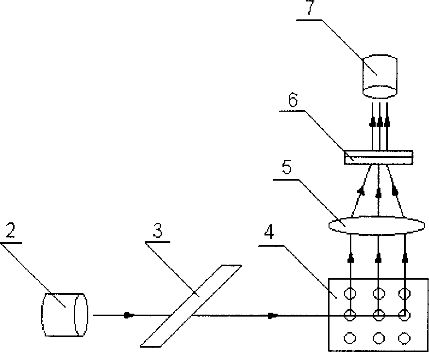
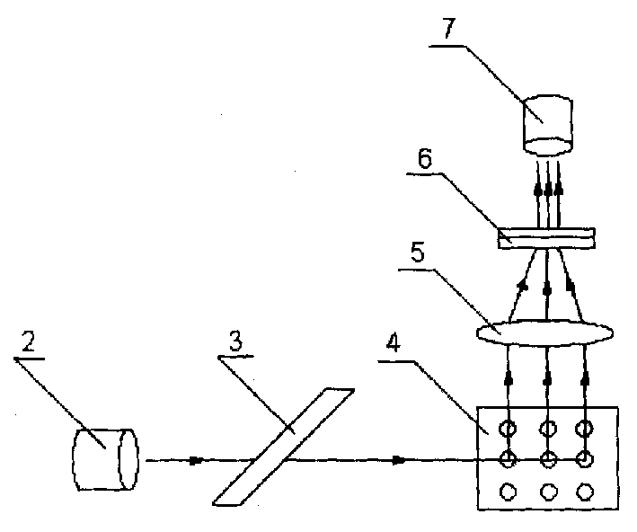
[0012] Such as figure 1 and figure 2 As shown, a fluorescence detector of the present invention is composed of a fluorescence excitation optical path and a fluorescence receiving optical path. The optical filter 3 and the sample cell 4 are constituted, and the described fluorescence receiving optical route is constituted by an aspheric mirror 5, a concave grating 6 and a photomultiplier tube 7, and an interference filter 3 is arranged at the front end of the excitation light source 2, and in the The front end of the filter 3 is provided with a sample cell 4, an aspheric mirror 5 is arranged on the sample cell 4, a concave grating 6 is arranged at the front end of the aspheric mirror 5, and a concave grating 6 is arranged at the front end of the concave grating 6. A photomultiplier tube 7 is provided, and the photomultiplier tube 7 is connected with an input and output data interface of a signal processor;

[0013] Specifically, the excitation light source 2 is a tungsten ha...


PUM

PropertyMeasurementUnit
wavelengthaaaaaaaaaa

Abstract

This invention discloses a fluorescence detector, which comprises fluorescence triggering light path and fluorescence receiving light path. The said fluorescence triggering light path is composed with layer source, interference filter and sample pool. The fluorescence receiving light path is composed of aspheric mirror, concave grating and multiplier phototube. There located an interference filter in front of laser source and sample pool in front of the filter and aspheric mirror in front of sample pool and concave grating in front of aspheric mirror and multiplier phototube in front of concave grating. The said multiplier phototube is connected with input or output interfaces of signal processor. Comparing with current technique, this invention adopts concave grating chromatic dispersion to greatly increase the wavelength accuracy and at the same time adopts aspheric reflection and effective signal multiplication to ensure the accuracy and specificity of wavelength and a reliable result.

Description

Technical field: [0001] The invention relates to an optical detection device, in particular to a fluorescence detection instrument for medical quantitative analysis. Background technique: [0002] The working principle of the fluorescence detector is: after a sample is irradiated by light of a specific wavelength, it will emit light longer than the excitation wavelength in a short time. This light is called fluorescence, and the fluorescence wavelength is related to the composition of the irradiated substance, The structure is related, and its fluorescence intensity is related to the concentration of the substance (or sample copy number). Within a certain concentration range, the fluorescence intensity is proportional to the concentration of the substance, and the concentration of the substance can be determined accordingly. [0003] In the existing technology, most of the fluorescence detectors adopt the filter-type divergent wavelength technology, the accuracy and specific...

Claims


Application Information

Patent Timeline
Patent Type & Authority Applications(China)
IPC IPC(8): G01J3/443G01N21/64
Inventor 温俊娥肖泉毅于效文
Owner 上海复生生物工程研究所有限公司
Why Eureka
Try Eureka