Check patentability & draft patents in minutes with Patsnap Eureka AI!

Phase-lock loop framework capable of avoiding frequency drift and jitter

A phase-locked loop and frequency technology, applied in the automatic control of power, electrical components, etc., can solve the problems of long-term frequency jitter, frequency is not accurate 125MHz, frequency drift, etc.

Inactive Publication Date: 2005-01-19
REALTEK SEMICON CORP
View PDF0 Cites 0 Cited by
  • Summary
  • Abstract
  • Description
  • Claims
  • Application Information

AI Technical Summary

Problems solved by technology

[0004] However, there is no simple multiplier relationship between the aforementioned 14.318MHz and 125MHz frequencies. Therefore, it is actually impossible to directly amplify 14.318MHz to obtain a frequency of 125MHz.
A feasible solution is to divide 14.318MHz by a very large number (for example, hundreds), and then amplify the frequency hundreds of times to around 125MHz, but this method will cause two problems: one is The long-term frequency jitter (Long-term Jitter) of the phase-locked loop magnified hundreds of times is relatively large, and the other reason is that the obtained frequency is not exactly 125MHz, so there will be the disadvantage of frequency drift (Frequency Drift)

Method used


Image

  • Phase-lock loop framework capable of avoiding frequency drift and jitter
  • Phase-lock loop framework capable of avoiding frequency drift and jitter
  • Phase-lock loop framework capable of avoiding frequency drift and jitter

Examples


Embodiment Construction

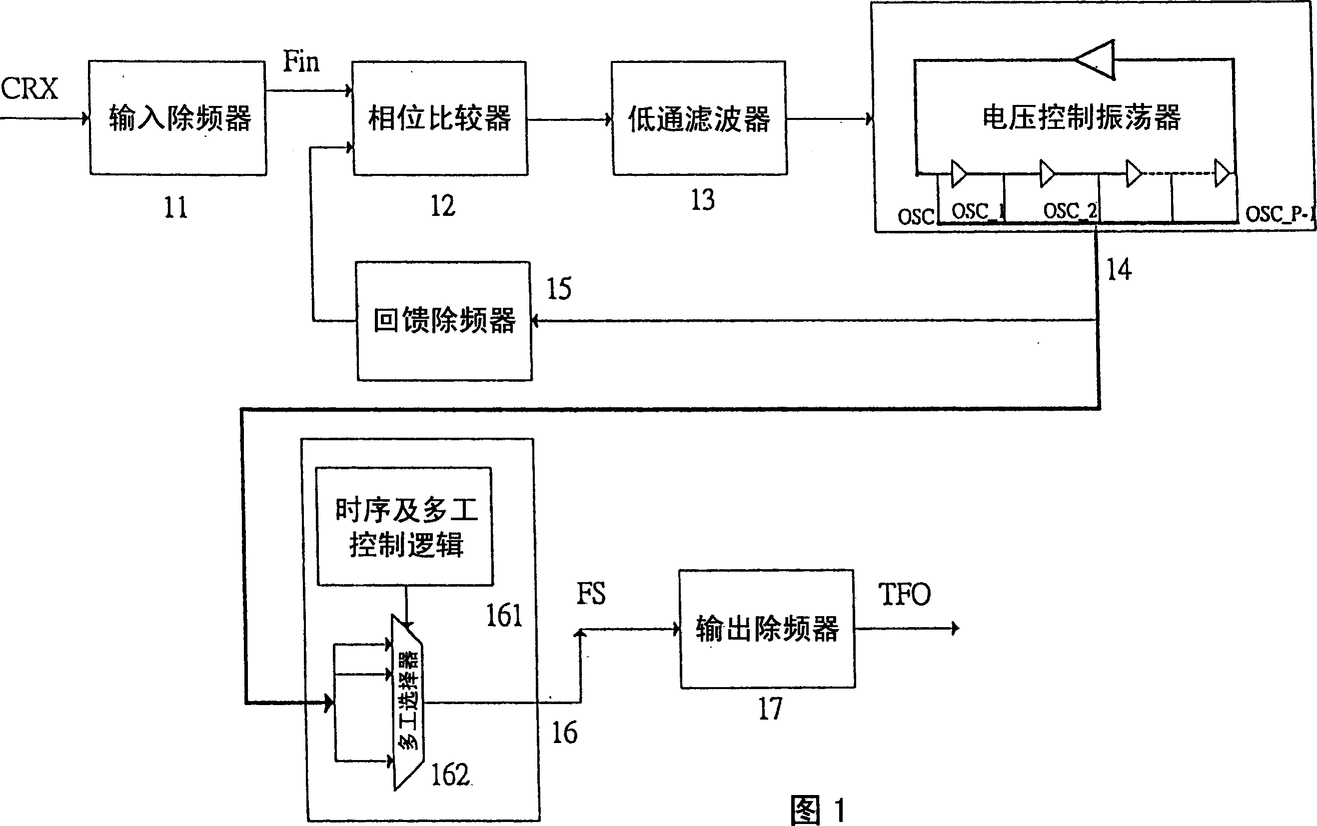
[0015] A preferred embodiment of the phase-locked loop structure that can avoid frequency drift and jitter of the present invention, please first refer to shown in Figure 1, it comprises a first frequency divider 11, a phase comparator 12, a low-pass A filter 13 , a VCO 14 , a second frequency divider 15 , a phase devourer 16 , and a third frequency divider 17 . Wherein, the circuit block composed of the first frequency divider 11 , the phase comparator 12 , the low pass filter 13 , the voltage controlled oscillator 14 , and the second frequency divider 15 is a phase locked loop.

[0016] In the aforementioned PLL loop, the first frequency divider 11 divides an input reference signal CRX by a divisor M (M is a positive integer); the second frequency divider 15 divides an input reference signal CRX by a divisor N (N is a positive integer) Perform frequency division on an oscillation signal OSC; the phase comparator 12 compares the output frequency division signal of the first f...


PUM


Abstract

The invention is a phase-locked loop structure able to eliminate frequency drift and shake, composed of a first frequency eliminator, a second frequency eliminator, a phase comparer, a low-pass filter and a voltage controlled oscillator, assorted with a phase swallower in it, able to accurately obtain the needed frequency by an input reference frequency, where the voltage controlled oscillator generates an oscillation signal and at least a phase shifted oscillation signal at the same frequency as that of the oscillation signal, the phase shifted oscillation signal differs by one phase from the oscillation signal, the phase swallower selects some phase to output to generate a phase swallowed frequency eliminated signal, which is in at least one time pulse of the oscillation signal and increased by at least one phase, and then has the frequency eliminated by a third frequency eliminator, thus able to generate an output signal at the needed frequency.

Description

technical field [0001] The present invention relates to the technical field of phase-locked loops, in particular to a phase-locked loop structure that can avoid frequency drift and jitter. Background technique [0002] With the rapid advancement of electronic technology, a variety of applications can be provided by various electronic products, for example, a LAN card can be used to provide a personal computer with a function of connecting to the Internet, or a video card can be used to provide multimedia functions and other applications. In the existing Ethernet communication protocol, 125MHz is used as the working frequency of its transmitter (Transmitter) and receiver (Receiver), but in many other applications, especially in TV images, It uses 14.318MHz as its operating frequency. Therefore, if the two applications are used on the same circuit board at the same time, it is inevitable to use two quartz oscillators to generate frequencies of 14.318MHz and 125MHz respectively...

Claims


Application Information

Patent Timeline
Patent Type & Authority Applications(China)
IPC IPC(8): H03L7/06
Inventor 江明澄黄睿政
Owner REALTEK SEMICON CORP
Features
  • R&D
  • Intellectual Property
  • Life Sciences
  • Materials
  • Tech Scout
  • Unparalleled Data Quality
  • Higher Quality Content
  • 60% Fewer Hallucinations
Learn More