Array type micro-electromechanic capacitor microphone

A technology of capacitive microphones and micro-electromechanical capacitors, applied in electrical components, transducer circuits, electrostatic transducer microphones, etc., can solve problems such as the difficulty of integrating capacitive microphones

Inactive Publication Date: 2005-01-19
TAIWAN CAROL ELECTRONICS
View PDF3 Cites 10 Cited by
  • Summary
  • Abstract
  • Description
  • Claims
  • Application Information

AI Technical Summary

Problems solved by technology

In fact, the directivity and signal-to-noise ratio of each condenser microphone are still slightly different, which makes it difficult to integrate the condenser microphones into

Method used


Image

  • Array type micro-electromechanic capacitor microphone
  • Array type micro-electromechanic capacitor microphone
  • Array type micro-electromechanic capacitor microphone

Examples


Embodiment Construction

[0043] Before explaining the technical details of the present invention in detail, it should be specifically stated that, for the sake of clarity, the following are all described with actual manufacturing processes, as well as various explanatory figures, units, materials, etc., but familiar sound energy, electrical energy, mechanical energy Theories and mutual conversion relations, micro-electro-mechanical system technology process, and microphone technicians can easily know that the present invention is not limited by the description of the actual process, and the numbers, unit materials, etc. The practical application of the present invention.

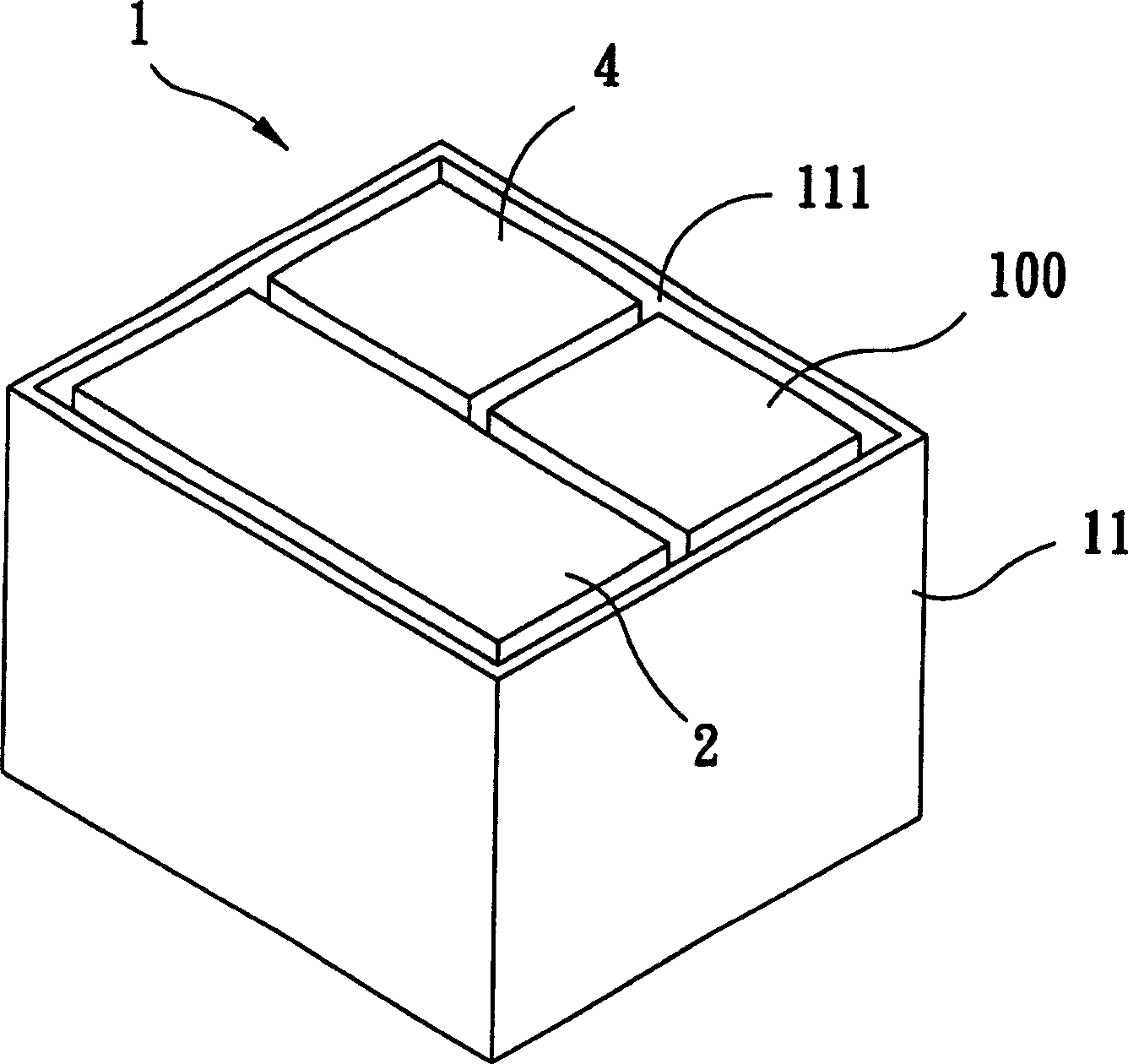
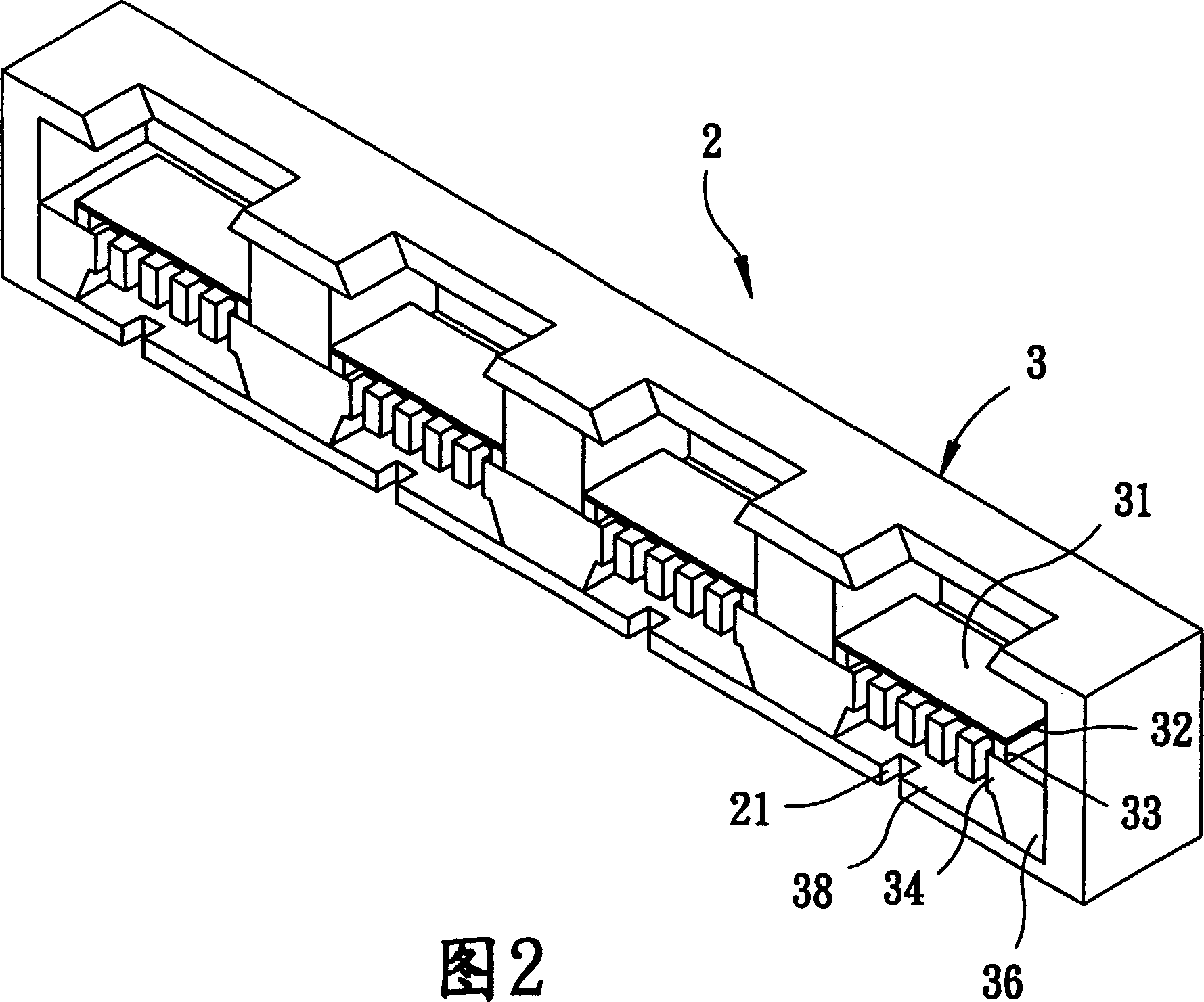
[0044] Such as figure 1 , as shown in FIG. 2 , an array microelectromechanical condenser microphone 1 of the present invention includes a base 11 , a condenser microphone device 2 , an analog computing device 4 , and a field effect transistor (FieldEmission Transistor; FET) 100 .

[0045] The base 11 defines an accommodating space ...


PUM


Abstract

The invention supplied a array mode micro-electromechanical capacitive microphone. It includes a foundation support and capacitive microphone device packaged in the foundation support. The capacitive microphone device contains basis material and a pair of analog calculus devices that run under the electronic signal produced by the unit of the capacitive microphone mentioned previously. Thus, the array micro-electromechanical capacitive microphone has high directivity and high signal to noise ratio.

Description

(1) Technical field [0001] The invention relates to a capacitive microphone, in particular to a capacitive microphone formed by micro-electromechanical system technology. (2) Background technology [0002] Microphones have long been widely used in electronic products such as mobile phones. With the development trend of the electronic products becoming thinner and smaller, the size of the microphone must also be continuously miniaturized. [0003] At present, there have been many related researches, rooted in the mid-1960s, using semiconductor manufacturing processes to manufacture micro-electromechanical systems (Micro-electromechanical Systems, MEMS) with mechanical structures on silicon wafers. Processing, control and many other functions, and at the same time must be extremely small in size and suitable for condenser microphones such as mobile phones and other electronic products. For example, Japanese Patent Application No. 11-331988 "microelectromechanical processing e...

Claims


Application Information

Patent Timeline
IPC IPC(8): H04R3/00H04R19/04
Inventor 白明宪黄士韦张昭智
Owner TAIWAN CAROL ELECTRONICS
Why Eureka
Try Eureka