Supercharge Your Innovation With Domain-Expert AI Agents!

D/a converter

一种数模转换器、奇数的技术,应用在数模转换器领域,能够解决不能获得误差抵消效果等问题

Inactive Publication Date: 2005-02-02
YAMAHA CORP
View PDF4 Cites 0 Cited by
  • Summary
  • Abstract
  • Description
  • Claims
  • Application Information

AI Technical Summary

Problems solved by technology

However, although the linearity error of this circuit is theoretically reduced to zero near the center, other error canceling effects cannot be obtained

Method used


Image

  • D/a converter
  • D/a converter
  • D/a converter

Examples


no. 1 example

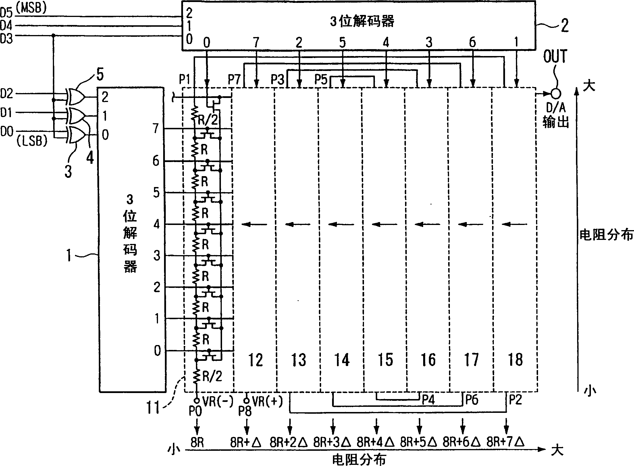
[0049] figure 1 is a block diagram showing the structure of the digital-to-analog converter according to the first embodiment of the present invention. The digital-to-analog converter receives data to be converted (hereinafter referred to as "conversion data") as a six-bit digital signal, converts the digital signal into an analog signal, and outputs the analog signal. exist figure 1 , reference numerals 1 and 2 denote 3-bit decoders, respectively. Through exclusive OR circuits 3 to 5, the 0th bit D0 (LSB) to the second bit D2 of the conversion data are input to the input terminal of decoder 1, and the third bit D3 to the fifth bit D5 (MSB) of the converted data are input at the same time Input to the input of decoder 2.

[0050] The voltage selection circuits 11 to 18 have the same structure, that is, each includes a resistor string composed of nine resistors connected in series and nine FETs (Field Effect Transistors). In each of the voltage selection circuits 11 to 18...

no. 2 example

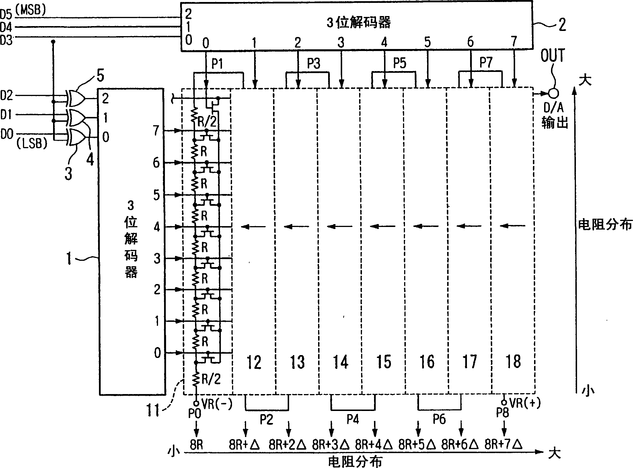
[0061] Figure 5 is a block diagram showing the structure of a digital-to-analog converter according to a second embodiment of the present invention. The second embodiment differs from the first embodiment in the connection form of each resistor string of the voltage selection circuit. Therefore, the connection form of the second embodiment will be mainly explained below.

[0062] That is, the uppermost end of the resistor string of the voltage selection circuit 11 is connected to the uppermost end of the resistor string of the voltage selection circuit 18, and the lowermost end of the resistor string of the voltage selection circuit 18 is connected to the resistor string of the voltage selection circuit 12. connected at the bottom. The uppermost end of the resistor string of the voltage selection circuit 12 is connected with the uppermost end of the resistor string of the voltage selection circuit 17, and the lowermost end of the resistor string of the voltage selection cir...


PUM


Abstract

A D / A converter formed on a semiconductor substrate includes a plurality of resistance strings which are provided between a low voltage terminal and a high voltage terminal, each of the resistance strings including a plurality of resistances connected in series. The resistance strings to be connected at odd-numbered positions are arranged on the substrate in order of increasing in a direction from a near side of the terminal to which the low voltage is applied to the far side thereof, and the resistance strings to be connected at even-numbered positions are arranged on the substrate in order of increasing in a direction from the far side of the terminal to the near side. A voltage at a junction point of the resistances constituting the resistance string is selectively output in accordance with input data to be converted.

Description

technical field [0001] The present invention relates to a digital-to-analog converter in which a resistor string is mounted on a semiconductor substrate. Background technique [0002] image 3 is a circuit diagram showing an example structure of a conventional digital-to-analog converter of resistor string type. The digital-to-analog converter receives data to be converted (hereinafter referred to as "conversion data") as a six-bit digital signal, converts the digital signal into an analog signal, and outputs the analog signal. exist image 3 , reference numerals 1 and 2 denote 3-bit decoders, respectively. [0003] Through exclusive OR circuits 3 to 5, the 0th bit D0 (LSB) to the second bit D2 of the conversion data are input to the input terminal of decoder 1, and the third bit D3 to the fifth bit D5 (MSB) of the converted data are input at the same time Input to the input of decoder 2. [0004] The voltage selection circuits 11 to 18 have the same structure, that is, e...

Claims


Application Information

Patent Timeline
Patent Type & Authority Applications(China)
IPC IPC(8): H03M1/76H03M1/06H03M1/68
CPCH03M1/765H03M1/0648H03M1/685H03M1/76
Inventor 户田彰彦
Owner YAMAHA CORP
Features
  • R&D
  • Intellectual Property
  • Life Sciences
  • Materials
  • Tech Scout
  • Unparalleled Data Quality
  • Higher Quality Content
  • 60% Fewer Hallucinations
Learn More